IFP-300 Series Manual — P/N LS10145-001SK-E:C 4/6/2022 29
Calculating Current Draw and Standby Battery Prerequisites for Installation
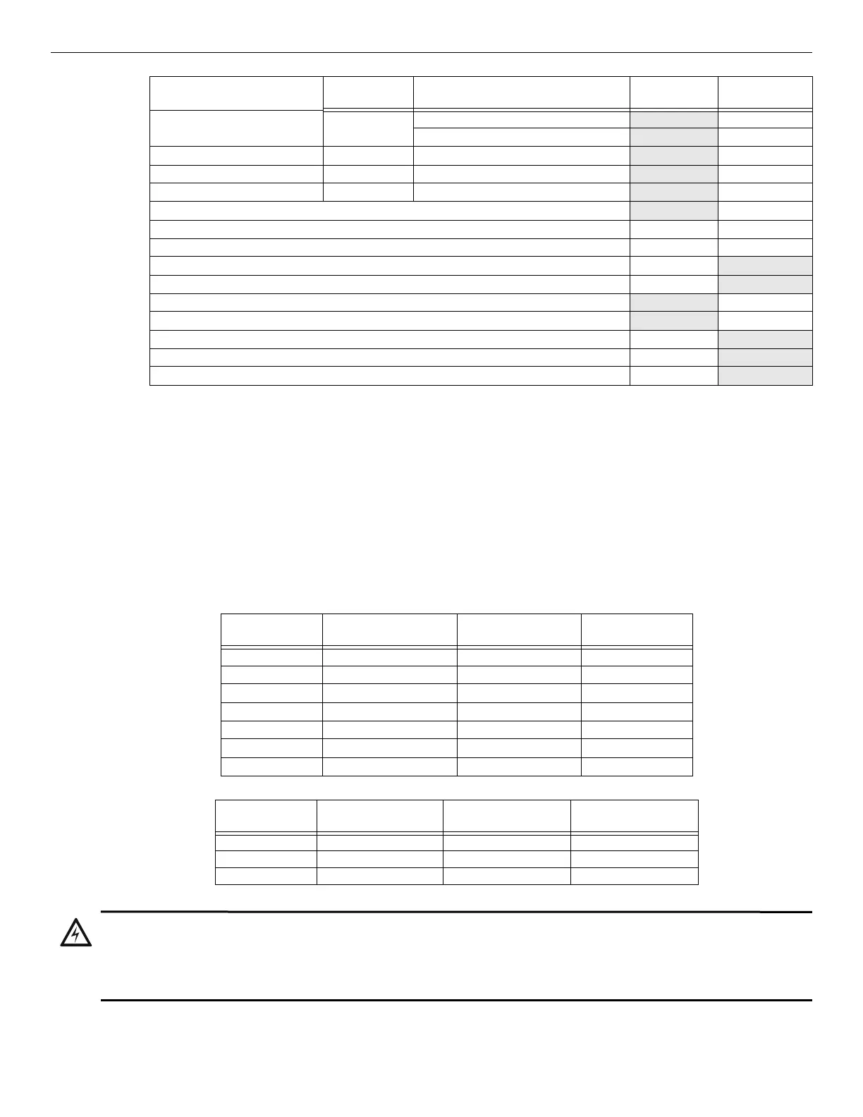
3.5.5 Maximum Battery Standby Load
Table 3.5 and Table 3.6 show the standby load calculations for the IFP-300 based on 24 and 90 hours of standby. The standby load calcula-
tions of line D in the Current Draw Calculation Worksheet must be less than the number shown in Table 3.5 and Table 3.6 for the selected
battery size, standby hour and alarm time. The numbers below have a built in 20% de-rating factor for the battery amp-hour capacity.
5495/5499 Power Supply Standby: 75 mA mA
Alarm: 205 mA
mA
Alarm: mA
mA
Alarm: mA
mA
Alarm: mA
mA
C Notification Appliances Current
mA
D Total current ratings of all devices in system (line A + line B + C) mA mA
E Total current ratings converted to amperes (line D x 0.001): A A
F Number of standby hours H
G Multiply lines E and F. Total standby AH AH
H Alarm sounding period in hours. (For example, 5 minutes = 0.0833 hours) H
I Multiply lines E and H. Total alarm AH
AH
J Add lines G and I. AH
Multiply by the Derating Factor 1.25
Total ampere hours required
6
AH
1 The FACP can only support 5 devices with LEDs on. The current draw has been added to the panels alarm current.
2 Total does not include isolator devices or accessory bases
3 If using 24 VDC aux power only. No standby or alarm current is needed for battery calculation if using 24 VAC, 120 VAC, or 240 VAC.
4 Maximum SBUS address capacity is determined by the amount of SBUS bandwidth consumed by each SBUS module. Refer to
Section 4.6.2 for SBUS limitations.
5 If using door holders, you do not need to consider door holder current for alarm/battery standby, because power is removed during that
time. However, during normal operation, door holders draw current and must be included in the 1.0A total current that can be drawn from
the panel.
6 Use next size battery with capacity greater than required.
Device # of Devices Current per Device
Standby
Current
Alarm Current
Table 3.4 Current Calculation Worksheet for SD Devices (Continued)
Rechargeable
Battery Size
24 hr Standby,
5 mins. Alarm
24 hr Standby,
15 min alarm
24 hr Standby,
20 min alarm
17AH 535mA 473mA 442mA
18AH 569mA 506mA 475mA
24AH 769 mA 706mA 675mA
33AH 1.07A 1.01A 975mA
35AH 1.14A 1.07A 1.04A
40AH 1.30A 1.24A 1.21A
55AH 1.80A 1.74A 1.71A
Table 3.5 :Maximum Battery Standby Loads for 24 Hour Standby
Rechargeable
Battery Size
90 hr Standby,
5 min alarm
90 hr Standby,
15 min alarm
90 hr Standby,
20 min alarm
33 AH N/A N/A N/A
40 AH 347mA 331mA 322mA
55 AH 480mA 464mA 456mA
Table 3.6 Maximum Battery Standby Loads for 90 Hour Standby (FM Applications Only)
WARNING: BATTERY SIZE
FARENHYT DOES NOT SUPPORT THE USE OF BATTERIES SMALLER THAN THOSE LISTED IN TABLE 3.5 AND
TABLE 3.6. IF YOU USE A BATTERY TOO SMALL FOR THE INSTALLATION, THE SYSTEM COULD OVERLOAD THE
BATTERY RESULTING IN THE INSTALLATION HAVING LESS THAN THE REQUIRED 24 HOURS STANDBY POWER. USE
TABLE 3.5 AND TABLE 3.6 TO CALCULATE THE CORRECT BATTERY AMP HOUR RATING NEEDED FOR YOUR
INSTALLATION. IT IS RECOMMENDED THAT YOU REPLACE BATTERIES EVERY FIVE YEARS.

 Loading...


