IFP-300 Series Manual — P/N LS10145-001SK-E:C 4/6/2022 37
RA-100 Remote Annunciator Installation Control Panel Installation
Wiring Distance Calculation Example:
Suppose a system is configured with the following SBUS modules:
2 - RA-1000 Fire Annunciators
1 - 5496 Intelligent Power Expander
1 - 5865 LED Fire Annunciator
1 - 5824 Parallel/Serial Interface
The total worst case current is calculated as follows:
Using this value, and referring to the Wiring Distance table, it can be found that the available options are:
• 370 feet maximum using 22 Gauge wire
• 938 feet maximum using 18 Gauge wire
• 1493 feet maximum using 16 Gauge wire
• 2,362 feet maximum using 14 Gauge wire
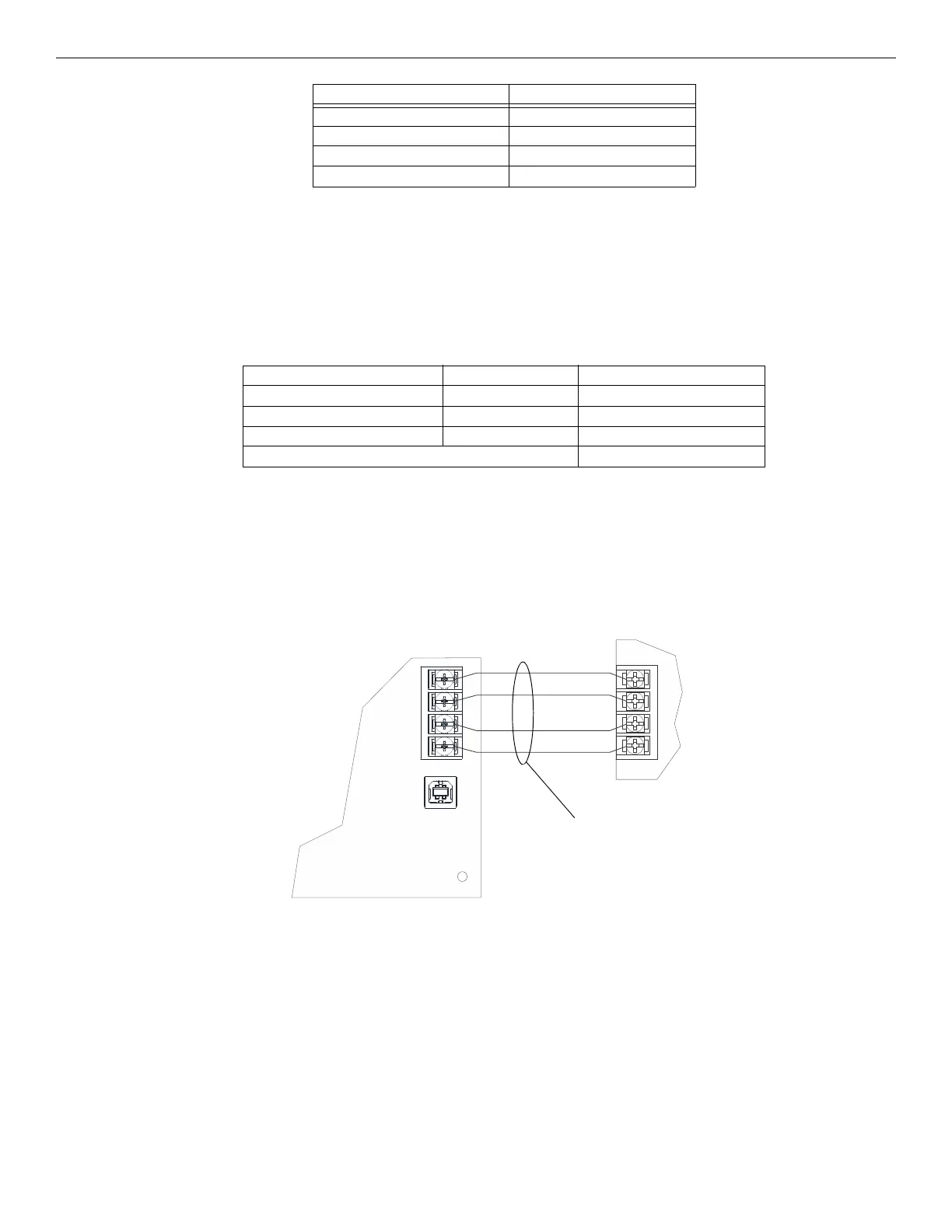
4.6.3 Wiring Configurations
Figure 4.11 illustrates SBUS, Class B configuration.
4.7 RA-100 Remote Annunciator Installation
The optional model RA-100 Remote Annunciator, is shown in Figure 4.12. The RA-100 can be surface or flush mounted. Up to 16 annunci-
ators can be added to the IFP-300 system in any combination.
Wire Gauge Ohms per 1000 feet (Rpu)
22 16.2
18 6.4
16 4.02
14 2.54
Table 4.5 Typical Wire Resistance Per 1000 ft.
RA-1000 Current Draw = 2 x 0.100 amps = 0.200 amps
RPS-1000 Current Draw = 1 x .010 amps = .010 amps
5865 Current Draw = 1 x 0.200 amps = 0.200 amps
5824 Current Draw = 1 x 0.040 amps = 0.040 amps
Total Worst Case Current Draw = 0.450 amps
Table 4.6 Worst Case Current Draw
supervised,
power-limited,
Class B
FACP
SBUS device
Figure 4.11 SBUS Class B Wiring

 Loading...


