50 IFP-300 Series Manual — P/N LS10145-001SK-E:C 4/6/2022
Control Panel Installation 5880 LED I/O Module
On connector P1, Pin 12 is a common open collector output for controlling a PZT. If used, the 5880 PZT will match the PZT pattern of the
on-board or remote annunciator.
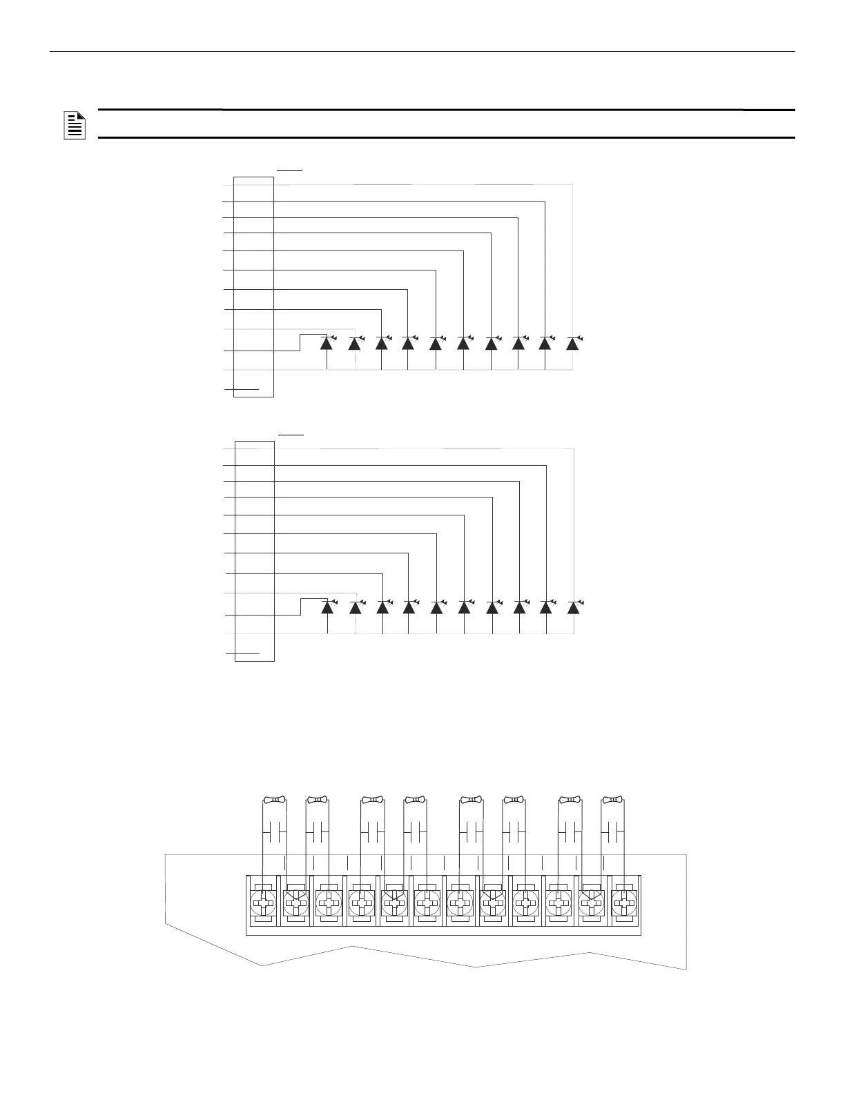
4.13.4 Dry Contact Wiring
The 8 input circuits on the 5880 board are for monitoring switch inputs. Any type of switch supported by the control panel can be used with
the 5880. For example, you can use a 5880 to monitor pull stations, water flow, tamper, reset, or silence switches.
Wire dry contacts as shown in Figure 4.36. Notice grouping of terminals; power terminals are shared by two inputs.
NOTE: The circuit connected to common “Open Collector Output” (last pin on P1) must be current limited so that no more than 100 mA of
current is allowed to flow into the open collector transistor.
Figure 4.35 5880 Board Layout
LED1
LED2
LED3
LED4
LED5
LED6
LED7
LED8
LED9
LED10
LED Power
no connection
Pin #
1
2
3
4
5
6
7
8
9
10
11
12
LED11
LED12
LED13
LED14
LED15
LED16
LED17
LED18
LED19
LED20
LED Power
no connection
P1
P2
Pin #
1
2
3
4
5
6
7
8
9
10
11
12
Cathode
LEDs
Anode
Cathode
LEDs
Anode
P3 and P4 are wired
the same as P2.
IN - 48 C+ IN - 47 IN - 46 C+
4.7kΩ EOL
resistors
supervised
wiring
5880
Figure 4.36 Dry Contact Wiring

 Loading...


