32 IFP-300 Series Manual — P/N LS10145-001SK-E:C 4/6/2022
Control Panel Installation Wiring Specifications
• Do not pull wires from different groups through the same conduit. If you must run them together, do so for as short a distance as
possible or use shielded cable. Connect the shield to earth ground at the panel. You must route high and low voltages separately.
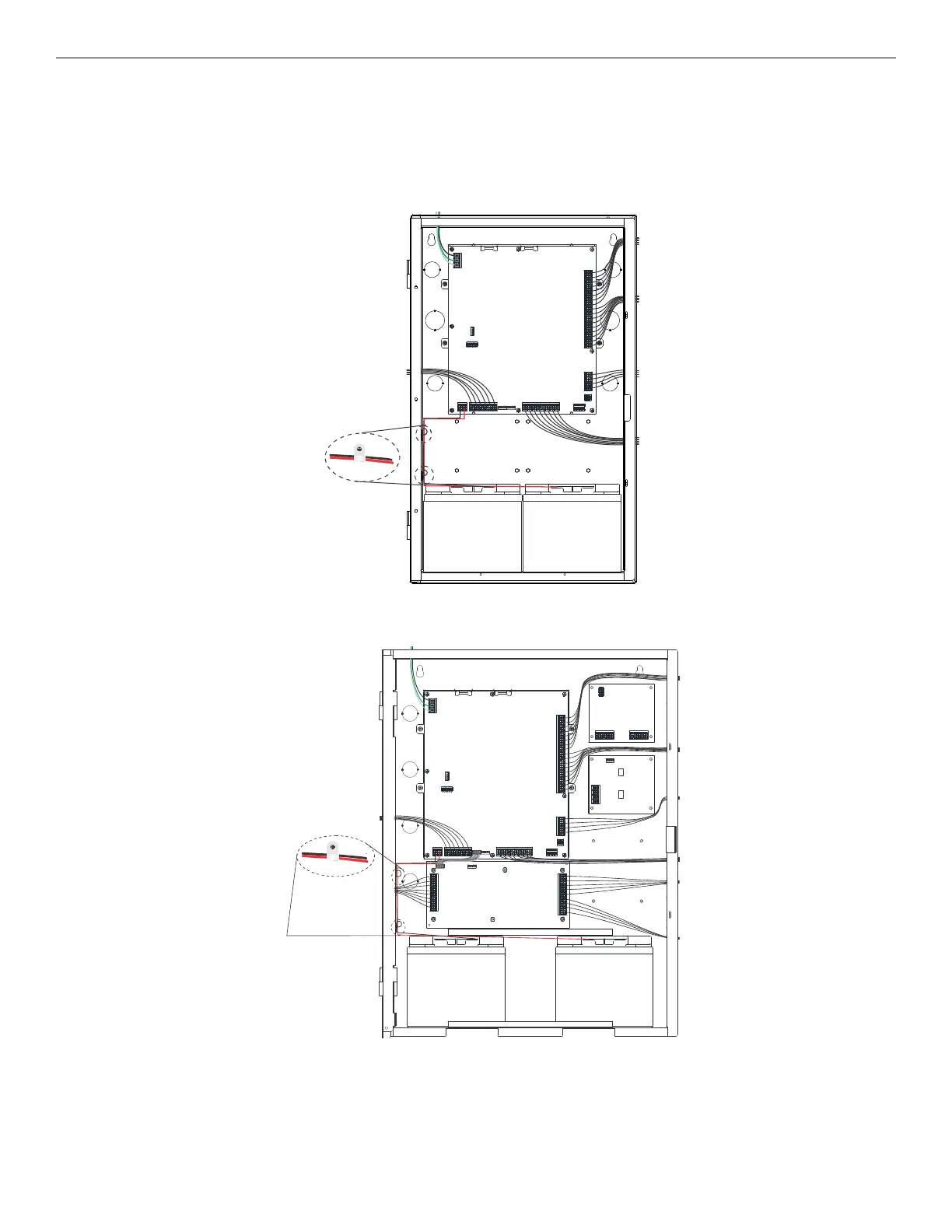
• Route the wiring around the inside perimeter of the cabinet. It should not cross the circuit board where it could induce noise into the
sensitive microelectronics or pick up unwanted RF noise from the high speed circuits. See Figure 4.3 for an example.
• High frequency noise, such as that produced by the inductive reactance of a speaker or bell, can also be reduced by running the wire
through ferrite shield beads or by wrapping it around a ferrite toroid.
Figure 4.3 Wire Routing Example for IFP-300
AC power
SLC
NAC/aux power circuits
relay circuits
SBUS
phone lines
0.25” spacing must be
maintained between each of
these circuit types, as well as
between power-limited and non-
power-limited circuits.
battery battery
AC power
SLC
NAC/aux power circuits
relay circuits
SBUS
phone lines
0.25” spacing must be
maintained between each of
these circuit types, as well as
between power-limited and non-
power-limited circuits.
battery battery
VBUS
relay circuit
network connections
Figure 4.4 Wire Routing Example for IFP-300ECS

 Loading...


