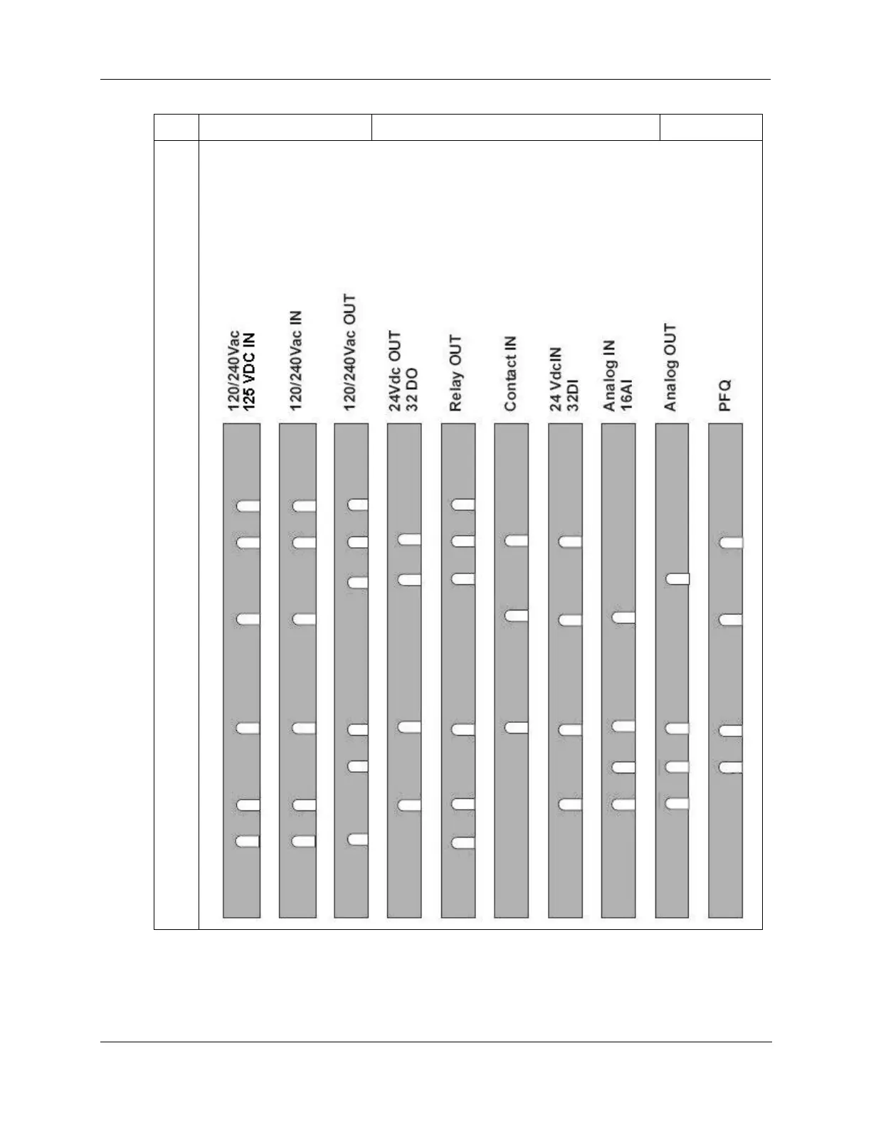
NOTE: In the diagram below, the white cut-outs represent the cut-outs on the modules that
accommodate tabs on the Terminal Block. That is, all key-tabs that line up with the white cut-
outs on the diagram should be retained, and all other tabs should be removed.
The orientation of the diagrams below corresponds to the picture of the terminal block, shown in
the previous picture.
Diagrams for I/O Module Key-Tabs

 Loading...


