188 HC900 Process & Safety Controller User and Installation Manual Revision 6
21 April 2017
I/O Module Diagnostic Indication
To indicate the type of diagnostic failure, the module’s status LED is flashed red with a number of quick
strobes followed by a long off time. Table 31 outlines the potential module diagnostics.
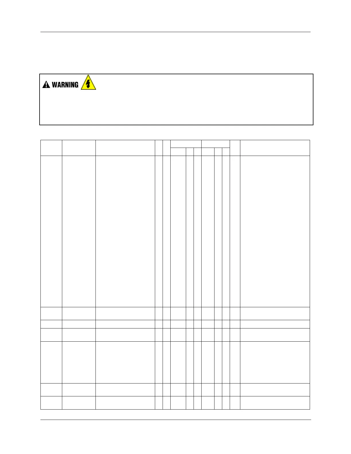
Hazardous voltages exist at terminal blocks.
AO8 and AO16 modules require at least one channel to be configured prior to a cold start for the module
to work properly. Subsequent channels then may be added with a hot start.
Failure to comply with these instructions could result in death or serious injury.
Table 31 – I/O Module LED Diagnostics
The module is in the failsafe state
because it is not receiving message
requests from the CPU or Scanner
at a rate that satisfies the configured
failsafe timeout.
1. If expansion I/O rack, go to step 2.
If no expansion I/O rack, go to
step 3.
2. Check the Scanner status LED
(see p. 183).
If it’s flashing 6 times, proceed
with step 3.
If it’s flashing some other red
status code, refer to Table 29
to solve that problem first.
If it’s flashing green, the module
probably is not required in the
configuration.
If it’s not on or steady, cycle
power to the scanner.
3. Make sure the module is the
correct one for the configuration.
4. Remove the module and check
for a bent pin, then reinsert the
module
5. Replace the module
6. Remove other modules and
replace one at a time until the
problem reoccurs. Most likely the
last module inserted needs to be
replaced.
7. Replace the rack.
EA ROM Failed its checksum
1. Remove/reinsert module.
1. Remove/reinsert module.
1. Remove the module and check
for a bent pin, then reinsert the
module
2. Measure power supply voltage. If
not correct, replace power supply.
3. Replace module
4. Replace rack
CRC failure of primary and backup
factory calibration
CRC failure of field calibration
values
1. Remove/reinsert module.

 Loading...


