84 HC900 Process & Safety Controller User and Installation Manual Revision 6
21 April 2017
I/O Module Installation Procedures
Table 14 – Connect Input/Output Wiring
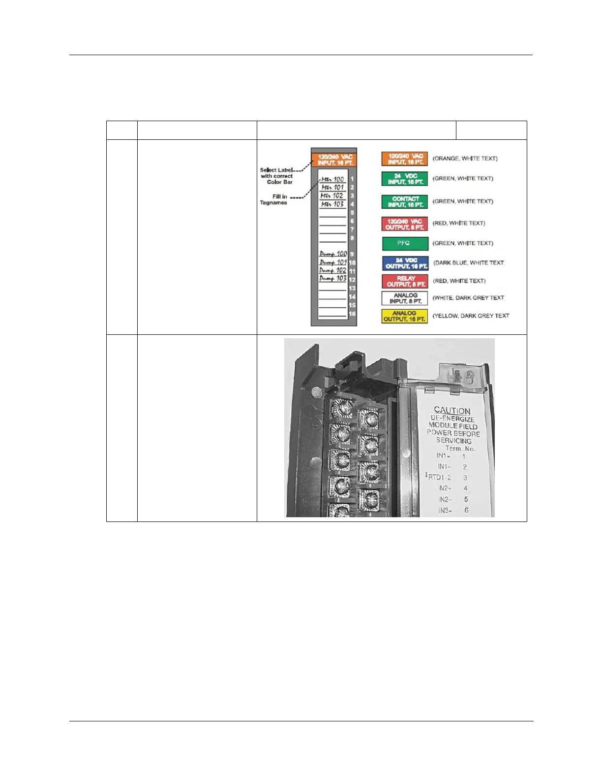
Using Rack #, Slot #,
Channel # data from a
Designer Software report,
fill in the tag names on the
Label for each configured
I/O Module. Module slot
position should take heat
de-rating into account.
See Heat Rise De-rating
page 52.
Be sure to use the
appropriate label for each
module type.
Place the appropriate label
supplied with the module
(tagname side out) into the
hinged door for each I/O
Module.
Slotted tabs, molded into
the door at top and
bottom, hold the label in
place.

 Loading...


