Revision 6 HC900 Process & Safety Controller User and Installation Manual 101
21 April 2017
Isolation
The outputs are grouped with 4 outputs per group (outputs 1-4, 5-8, 9-12, 13-16). Groups are isolated from
each other; outputs are non-isolated within each group.
Shield Grounding
Shields must be grounded as described under Shield Grounding at the beginning of this section.
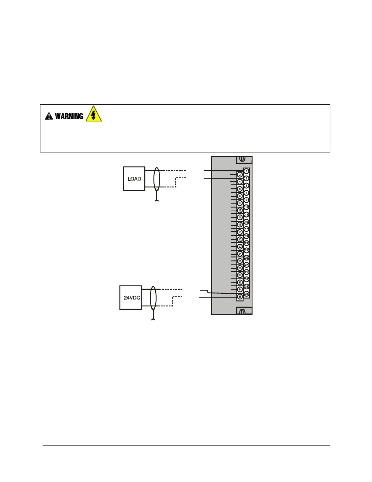
Hazardous voltages exist at terminal blocks.
Using switches at field devices disconnect the field wiring form power sources before servicing.
Failure to comply with these instructions could result in death or serious injury.
OUT 3+
OUT 4+
OUT 5+
OUT 6+
OUT 7+
OUT 8+
OUT 2+
OUT 3-
OUT 4-
OUT 5-
OUT 6-
OUT 7-
OUT 8-
OUT 2-
NC
NC
NC
NC
NC
NC
NC
NC
NC
NC
NC
NC
NC
NC
NC
NC
NC
NC
OUT 1+
OUT 1 -
+
-
24VDC+
24VDC-
+
-
Figure 51 – 8 channel Analog Output Wiring Diagram

 Loading...


