24 HC900 Process & Safety Controller User and Installation Manual Revision 6
21 April 2017
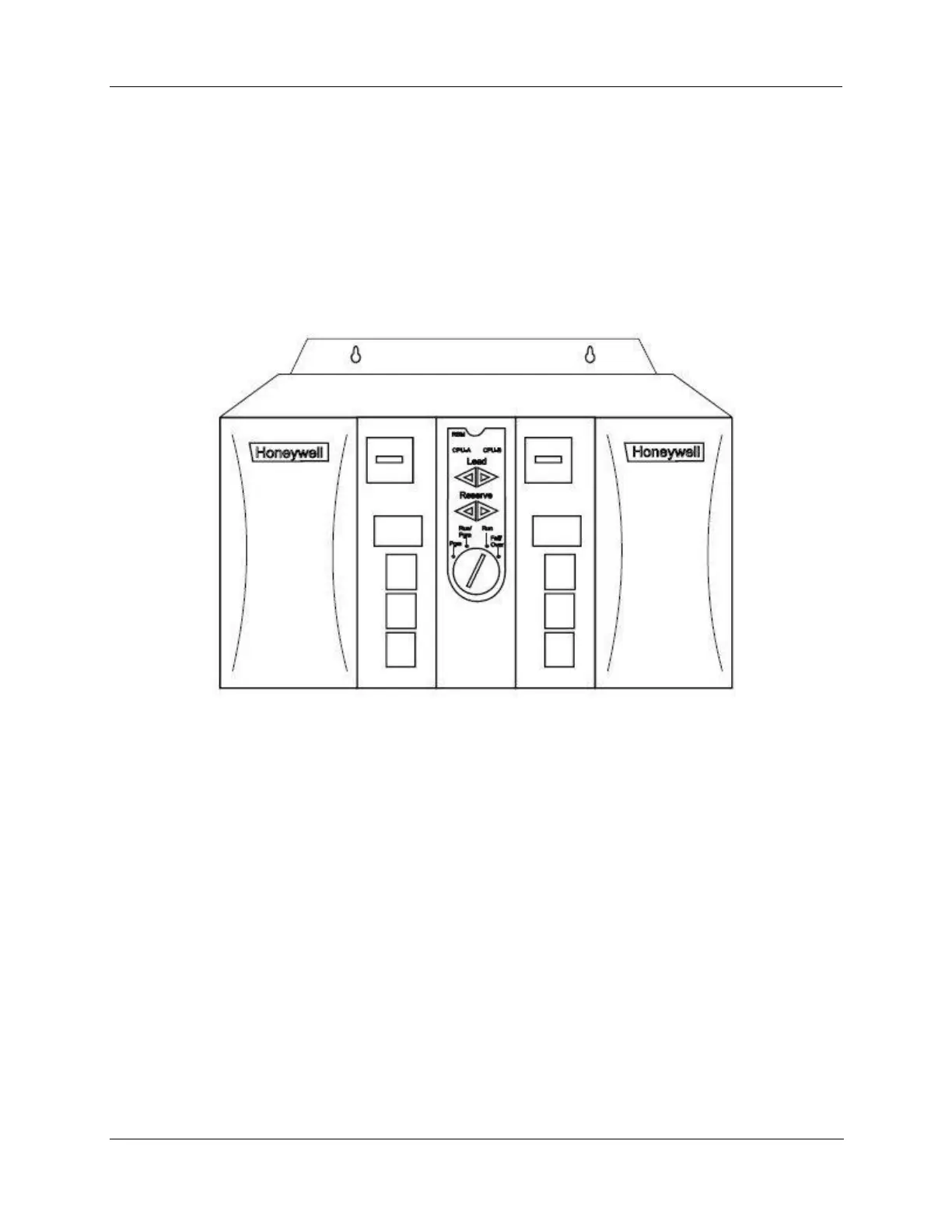
HC900 Redundant Controller Rack
A HC900 Redundant Controller is shown in the following figure.
1. Rack
2. Redundancy Switch Module (RSM) . Interface between Lead/Reserve controllers.
3. Lead/Reserve controllers. Two C75 CPUs, designated “CPU-A” (left), “CPU-B” (right).
4. Two 900P01-xxxx or 900P02-xxxx Power Supplies.
Figure 7 – Redundant Controller Rack Components

 Loading...


