100 HC900 Process & Safety Controller User and Installation Manual Revision 6
21 April 2017
Failure to comply with these instructions could result in death or serious injury.
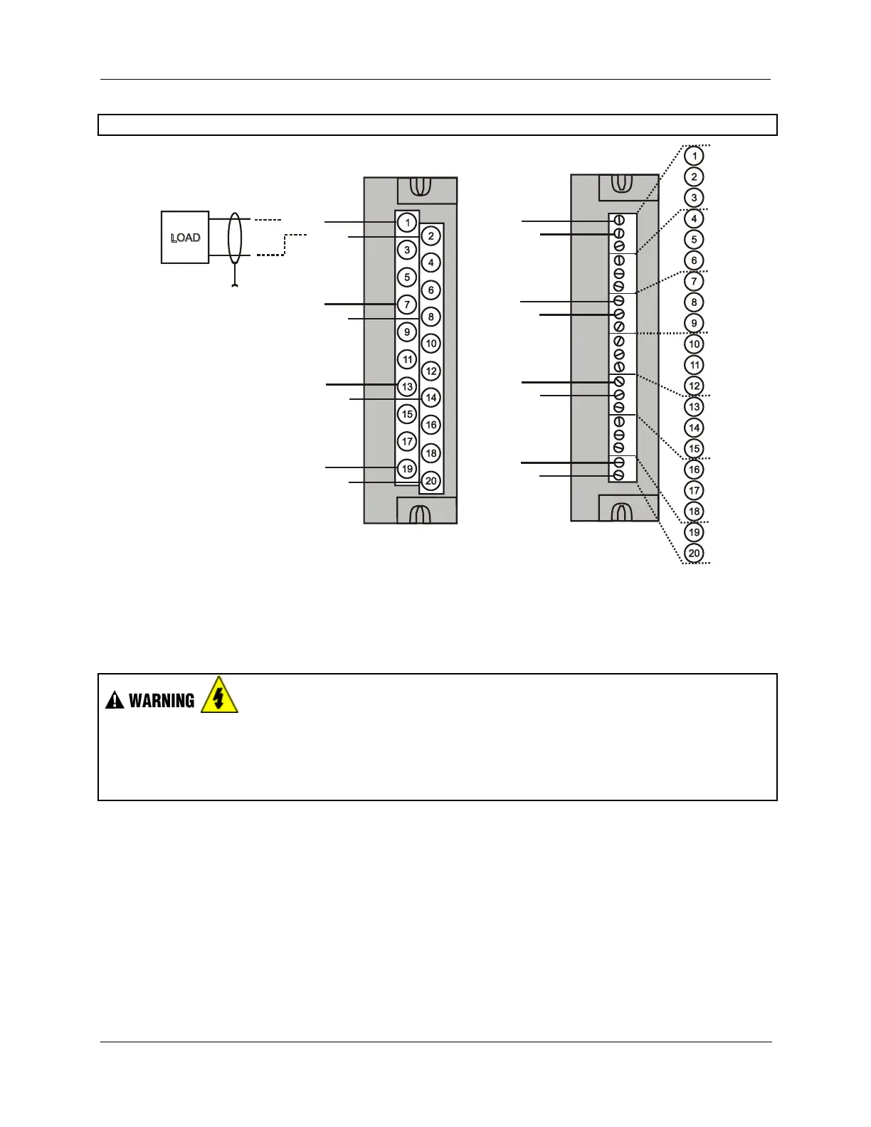
OUT 1+
OUT 1 -
OUT 2+
OUT 2 -
OUT 3+
OUT 3 -
OUT 4+
OUT 4 -
+
-
OUT 1+
OUT 1 -
OUT 2+
OUT 2 -
OUT 3+
OUT 3 -
OUT 4+
OUT 4 -
Figure 50 – 4 channel Analog Output Wiring Diagram
8 and 16 channel Analog Output Module Wiring
Hazardous voltages exist at terminal blocks.
AO8 and AO16 modules require at least one channel to be configured prior to a cold start for the module
to work properly. Subsequent channels then may be added with a hot start.
Failure to comply with these instructions could result in death or serious injury.
Examples of high level Analog Output Module wiring are shown in Figure 51 and Figure 52.
Specifications for this module and for other modules are given in the Specifications manual. SIL
applications require an external series relay used to ensure outputs achieve failsafe action. See HC900
Process & Safety Controller Safety Manual for additional details.
Before installing, be sure to determine power requirements. See page 46 and 87.
Requires Low Voltage Euro style 36-terminal terminal block.

 Loading...


