Revision 6 HC900 Process & Safety Controller User and Installation Manual 31
21 April 2017
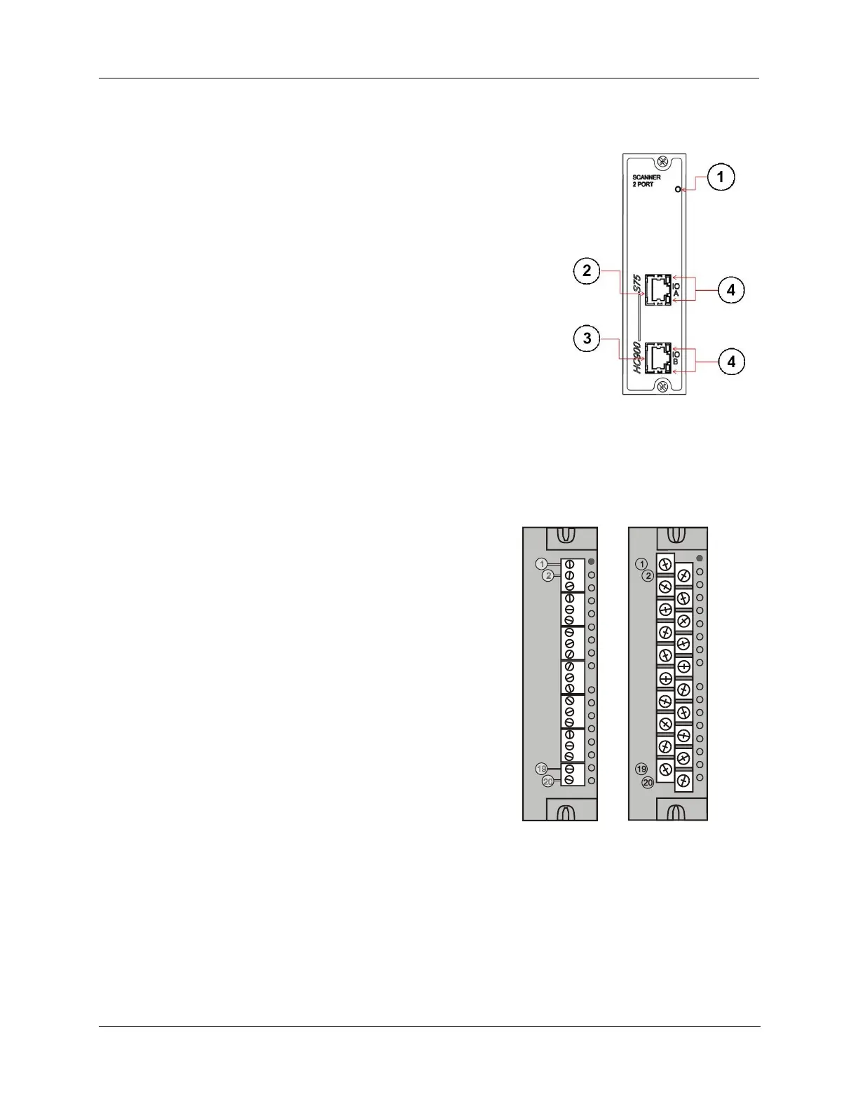
Scanner 2 Module (S75/S75S only)
900S75, Scanner 2 Module is shown in Figure 15.
The dual ports provide redundancy through the 2 CPUs. Features at the front of
the module include:
1. LED status/diagnostic indicator for scanner functions.
2. I/O port A. Private Ethernet 10/100 Base-T Port. Connects directly to I/O port
on CPU-A (or indirectly through a switch).
3. I/O port B. Private Ethernet 10/100 Base-T Port. Connects directly to I/O port
on CPU-B (or indirectly through a switch).
4. LED status/diagnostic indicators for communications functions
Figure 15 – Scanner 2 Module
Input/Output Modules
I/O module types:
16 point high level analog input module: each point is configurable for V or mA. Point-to-point galvanic
isolation, chassis to input galvanic isolation.
4 point galvanic isolated analog output module: Supports
from 0 to 20mA each, chassis to output galvanic isolation.
8 or 16 point analog output module: Supports from 0 to
20mA each. Galvanically isolated in groups of 4 channels,
galvanically isolated chassis to output channels.
16 point digital input modules: Contact closure type, DC
voltage and AC voltage types. Galvanically isolated chassis
to input.
32 point digital input module: DC voltage. Galvanically
isolated in two groups 1-16, 17-32. Galvanically isolated
chassis to input channels.
8 point AC (sourcing type) or 16 point DC digital output
modules (sinking type). Galvanically isolated output
channels to chassis and channel to channel in two groups.
32 point digital output: DC voltage (sourcing type).
Galvanically isolated output channel to chassis and
output to output in two groups.
8 point relay output module: four form C type and four form A type relays. Galvanically isolated output
to chassis and output to output.
8 point Universal Analog Input module. Galvanically isolated input to chassis and input to input. With
the exception of RTD types which has four groups of isolation 1-2,3-4,5-6,7-8.
4 channel Pulse/Frequency/Quadrature I/O module. Galvanically isolated channel to chassis.
Figure 16 - I/O Module Terminal Block

 Loading...


