92 HC900 Process & Safety Controller User and Installation Manual Revision 6
21 April 2017
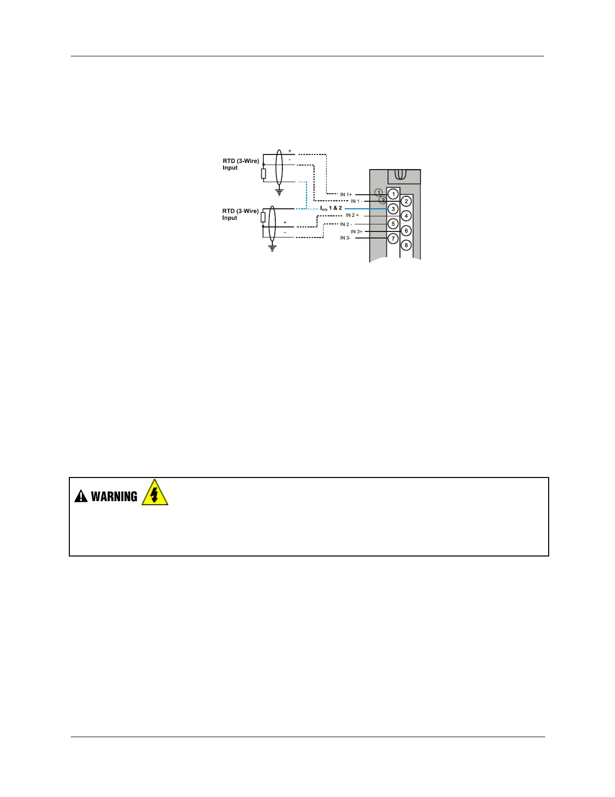
Figure 42 and Figure 46 show examples of RTD input wiring (2-wire and 3-wire RTDs). Four-wire RTD
inputs are not available.
Figure 42 – RTD Inputs
OHMs Inputs
Ohms inputs are wired similar to 2-wire RTD inputs. That is, they require a current source, and thus must
use one of the I
RTD
current sources. Also, two terminals are jumpered together as they are for two-wire
RTD inputs.
Analog channels wired for Ohms inputs differ from RTD inputs in these aspects:
Ohms inputs connect to variable resistance devices other than RTDs, and
Ohms inputs are configured in Designer Software as Ohms inputs, rather than as RTD inputs.
Examples of wiring for resistance inputs are given in Figure 46 .
Shield Grounding
Shields must be grounded as described under Shield Grounding at the beginning of this section.
Hazardous voltages exist at terminal blocks.
Using switches at field devices disconnect the field wiring from power sources before servicing.
Failure to comply with these instructions could result in death or serious injury.

 Loading...


