78 HC900 Process & Safety Controller User and Installation Manual Revision 6
21 April 2017
I/O Module Installation and Wiring
Overview
This section contains descriptions of and procedures for installing I/O Modules in controller racks
(C30/C30S, C50/C50S, C70/C70S, models) and in I/O expansion racks (S50/S50S, S75/S75S only).
Module Placement in Racks
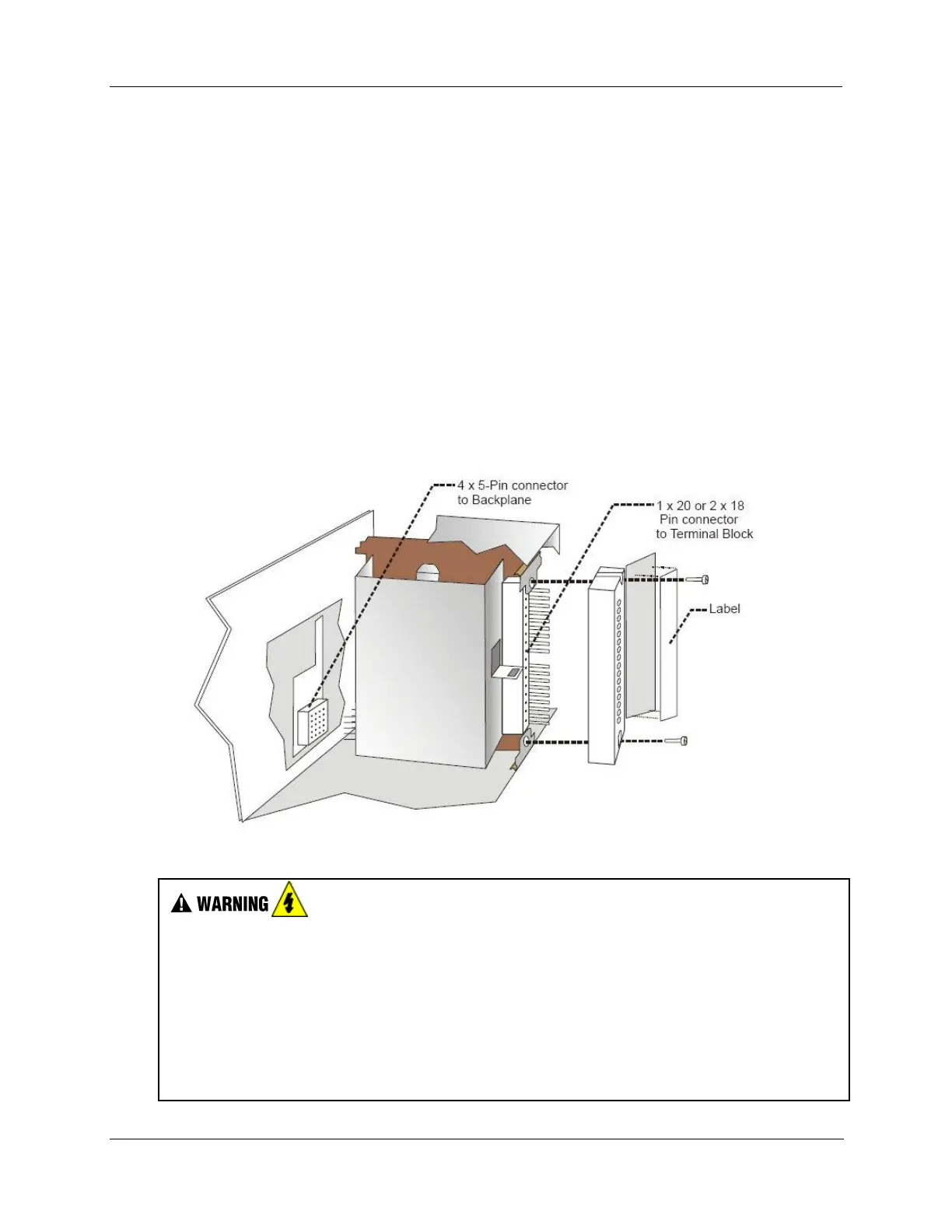
Each input or output module is placed in an I/O slot in a rack as shown in Figure 37.
Each “slot” in a rack includes a set of guides that locate the circuit board in the rack and a 20-pin (4 x 5)
socket in the backplane that receives the associated 4 x 5-pin plug at the back of the I/O module.
At the front of each I/O module, a 20 or 36 pin plug receives the associated socket on the back of a terminal
block. When the I/O module is inserted into the rack and the terminal block is placed on the circuit board,
two captured screws in the terminal block are fastened to metal tabs on the rack.
Figure 37 – I/O Module Installation
Do not use an input/output terminal block if the terminal block is damaged, if the door is
missing, or if one or both mounting screws are missing.
Always tighten both terminal block screws to proper torque settings before applying field
power to the module. Torque to 0,4 - 0,5 Nm (3.5 – 4.4 Lb-In.)
Do not apply energized (“live”) field wiring to an input/output module that is not installed in
one of the racks in the HC900 Controller.
Do not operate the controller without a Protective Earth connection.
Failure to comply with these instructions could result in death or serious injury.

 Loading...


