202 HC900 Process & Safety Controller User and Installation Manual Revision 6
21 April 2017
Table 38 – I/O Module Replacement
Removal or Insertion Under Power of an I/O module is an option, but if operating circumstances permit,
disconnecting power from the rack is the preferred option. Plan and develop an action sequence before
beginning the replacement procedure. Primary considerations include:
When replacing I/O module, the voltages to the modules must be disconnected at the field device
before removing the terminal block from the module.
Loss of control/monitoring in a running process - Each signal at each of the terminals for an I/O
module has a specific function. Any or all of the signals may be vital for safely controlling a process.
Determine the functions of all signals to the modules and know the potential consequences of losing each.
If possible, transfer control to alternate mechanisms; otherwise, bring the process to a safe and controlled
shutdown.
Disconnect all signals from power sources, using (user-supplied) switches at field devices. Use a
meter to ensure that all voltages are disconnected.
If a power-down replacement procedure is opted, also disconnect power from the rack, using the
(user-supplied) switch in the site AC power source.
Loosen the captive screws at top and bottom of the module; loosening the screws will cause the
terminal block to be partly extracted from the module connector. Remove the terminal block
from the module.
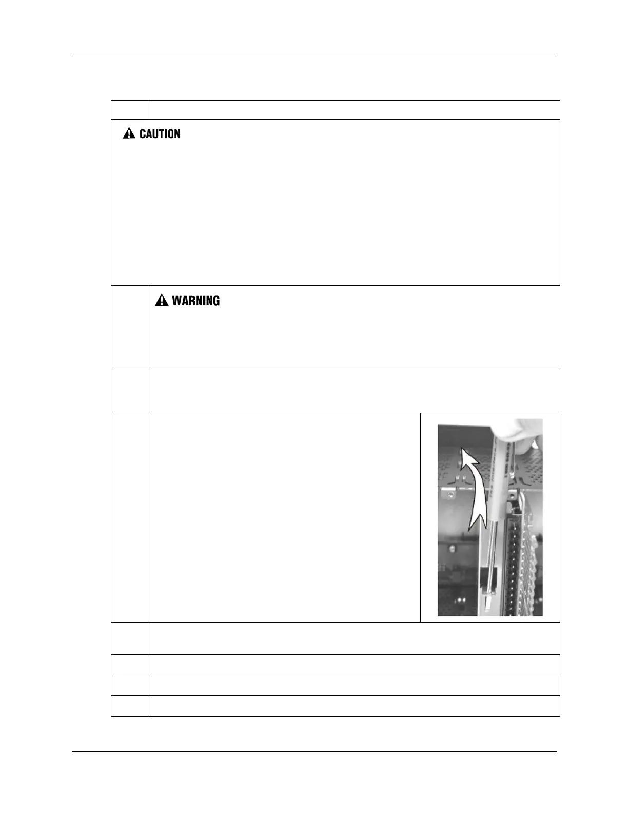
Using the extractor loop on the cover on the module, pull the
module from the slot as shown in the illustration at right.
As shown in the illustration, a long flat-tip screwdriver is used
as an extraction lever.
Insert the screwdriver tip into the extraction tab on the front of
the module cover, and rotate the screwdriver handle toward the
back, using the top edge of the rack as a fulcrum.
Verify that the replacement module is of the proper type. Then, carefully insert it into the slot in
the rack so as to make proper contact with the connector in the backplane.
Replace the terminal block on the module.
If the rack was powered-down for the procedure, restore power to the rack.
Re-connect signals to field devices.

 Loading...


