Revision 6 HC900 Process & Safety Controller User and Installation Manual 81
21 April 2017
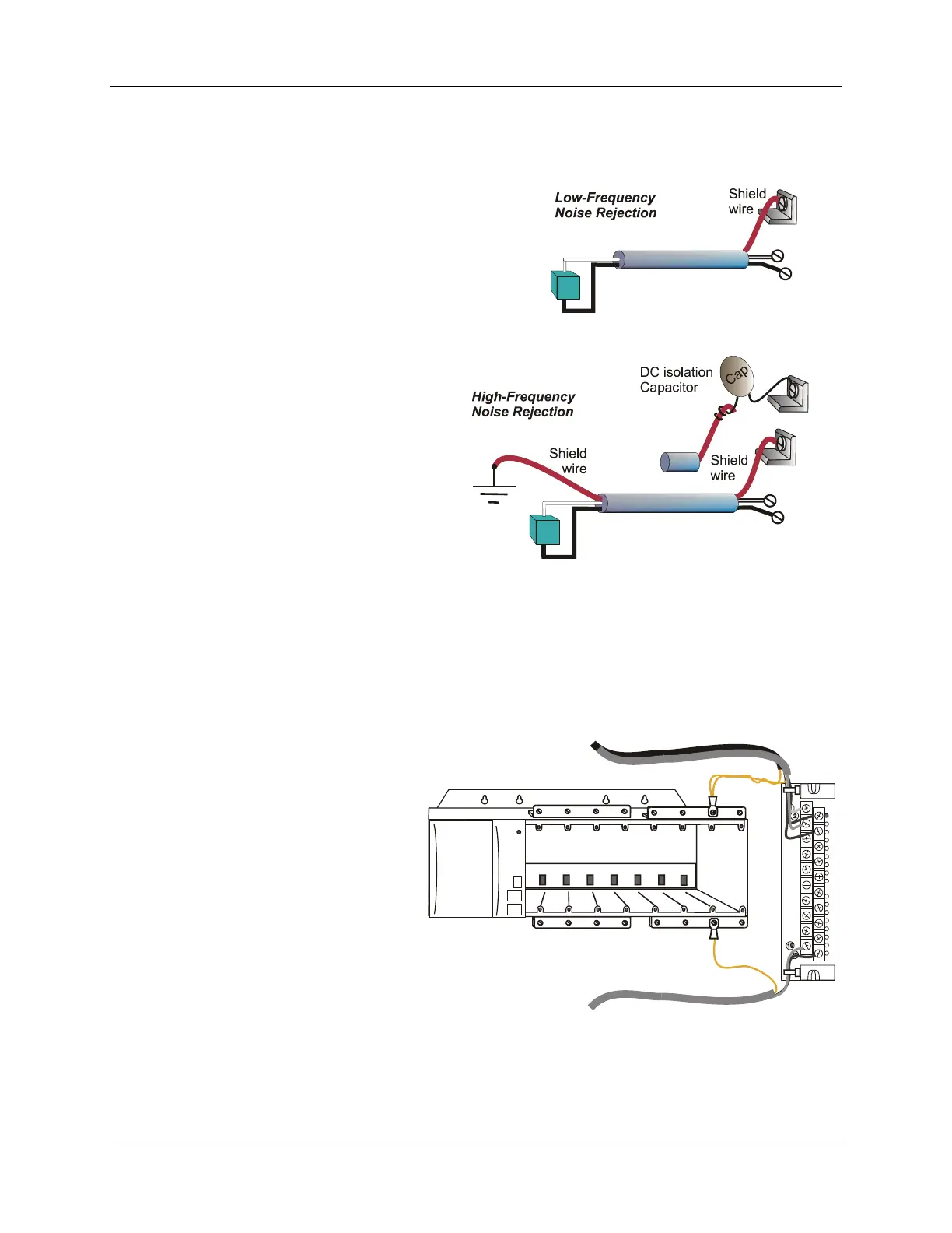
Signal Grounding (
Figure 39)
The shield for each input should be grounded
at the grounding bar (optional) at the top or
bottom of each rack as indicated in Figure 40.
For low-frequency noise rejection, I/O wiring
shields should be grounded only at the
controller end.
For high-frequency noise rejection, shields
should be grounded at the controller and at
the field device. If the ground voltage
potential at the field device is different from
that at the controller, a DC isolation capacitor
should be used between the shield and the
grounding bar on the rack.
Figure 39 – Signal-Wire Grounding
Aluminum grounding bars for I/O wiring are available as options. When selected for use, they are fastened
to the top and/or bottom of each rack, as indicated in Figure 40. To enable connection of multiple ground
wires with a single screw, the wires can be twisted together and secured with a wire lug.
To facilitate module replacement, it is advisable in most cases to route all wiring through either the top or
the bottom of the terminal block. This
allows the terminal block to pivot up or
down, allowing ready access to the
module, and is the preferred method
for a limited number of wires.
For a larger number of wires, or for
wires of a heavier gauge, it is advisable
to route some wires through the top of
the terminal block, and some through
the bottom, as indicated in Figure 40.
In this case, it is necessary to adjust
wire length so as to ensure adequate
flexibility of the twisted wires and to
provide clearance sufficient to remove
the I/O module.
Figure 40 – Wire-Shield Grounding

 Loading...


