EasyManuals Logo

Honeywell HC900 User And Installation Manual

Honeywell HC900
274 pages
To Next Page IconTo Next Page
To Previous Page IconTo Previous Page
Page #166 background imageLoading...
Page #166 background image
152 HC900 Process & Safety Controller User and Installation Manual Revision 6
21 April 2017
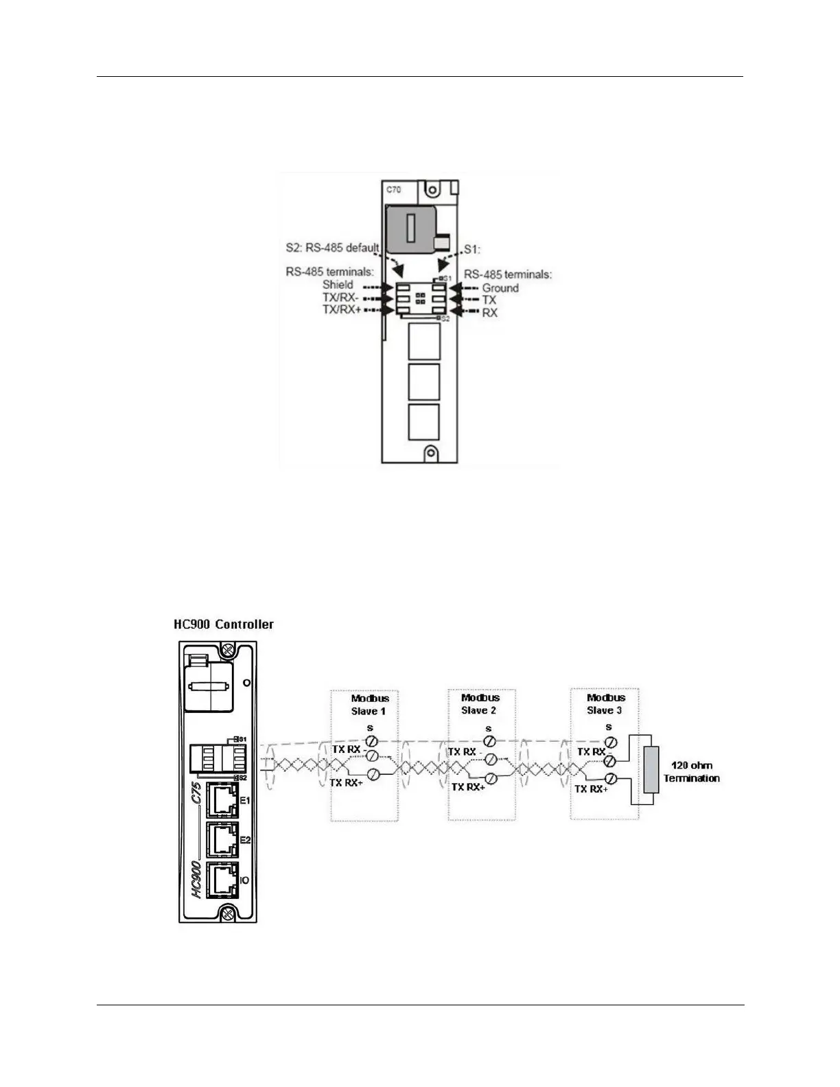
Connecting the HC900 Controller to Modbus device(s)
RS-485 Modbus connections
Use Designer software to configure the controller’s galvanically isolated RS-485 port as a master or slave.
Install resistor as shown for terminated devices except HC900. For terminating HC900, do not install
resistor. Instead, set internal DIP switches for termination (page 42).
When using the HC900 XYR5000 transmitter function blocks and RS-485 serial communications ports,
connect Base Stations to the HC900 controller as shown in Figure 80.
Figure 80 - RS-485 Modbus slave wiring

Table of Contents

Other manuals for Honeywell HC900

Questions and Answers:

Question and Answer IconNeed help?

Do you have a question about the Honeywell HC900 and is the answer not in the manual?

Honeywell HC900 Specifications

General IconGeneral
SeriesHC900
RedundancyOptional
Programming LanguageFunction Block Diagram, Ladder Logic, Structured Text
InputsAnalog, Digital
OutputsAnalog, Digital, Relay
DisplayOptional
ControlPID, Advanced Control
Power Supply24V DC or 100-240V AC
Storage Temperature-40°C to 85°C
Humidity5% to 95% non-condensing
Communication ProtocolsModbus, Ethernet

Related product manuals