Revision 6 HC900 Process & Safety Controller User and Installation Manual 29
21 April 2017
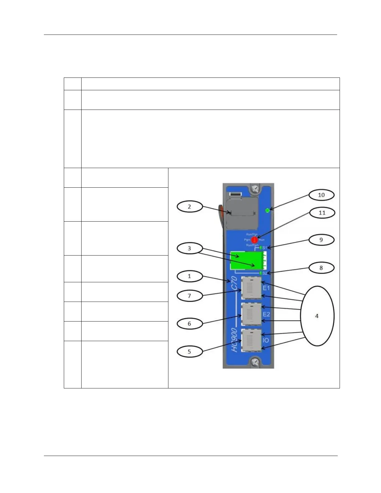
Controller Module
C30 and C30S, C50 and C50S, C70 and C70S, C75 and C75S Controllers share the same features, with exceptions
noted.
CPU model number (C30 and C30S, C50 and C50S , C70 and C70S, C75 and C75S).
Lithium battery (battery tray), which is readily accessible for field replacement. Battery tray on
Controllers C30/C30S, C50/C50S, C70/C70S, and C75/C75S.
Serial Interface Ports
For legacy systems, two serial ports, S1 and S2, each configurable as RS-232 or RS-485 provides
interfaces to a PC, external modem, Modbus devices or Operator Interfaces.
For new systems, two galvanically isolated RS-485 serial ports, S1 and S2 provide interfaces to PC
using RS-485 to usb cable. External modem or Modbus devices may be interfaced using RS-485 to
RS-232 converter. RS-485 interfaces to PC, Control Stations or Modbus devices/host.
Ethernet LED status indicators
for communications functions
Figure 12 – Controller Module
Connection to I/O port of
Scanner Module.
C50/C50S/C70/C70S,
C75/C75S only
Second Ethernet (E2) Host
Connection to PC applications
or peer HC900 controllers.
C70/C70S/C75/C75S only
First Ethernet (E1) Host
Connection to PC applications
or peer HC900 controllers
LED status/diagnostic indicator
for serial port S2 (left)
LED status/diagnostic indicator
for serial port S1 (right)
LED status/diagnostic indicator
for controller module
Mode switch (Pgm, Run/Pgm,
Run). Not present on
C75/C75S; see RSM
Redundant controller rack contains two C75s or C75Ss. Left CPU is designated CPU-A, right CPU is CPU-B; either
CPU can be Lead.

 Loading...


