Revision 6 HC900 Process & Safety Controller User and Installation Manual 99
21 April 2017
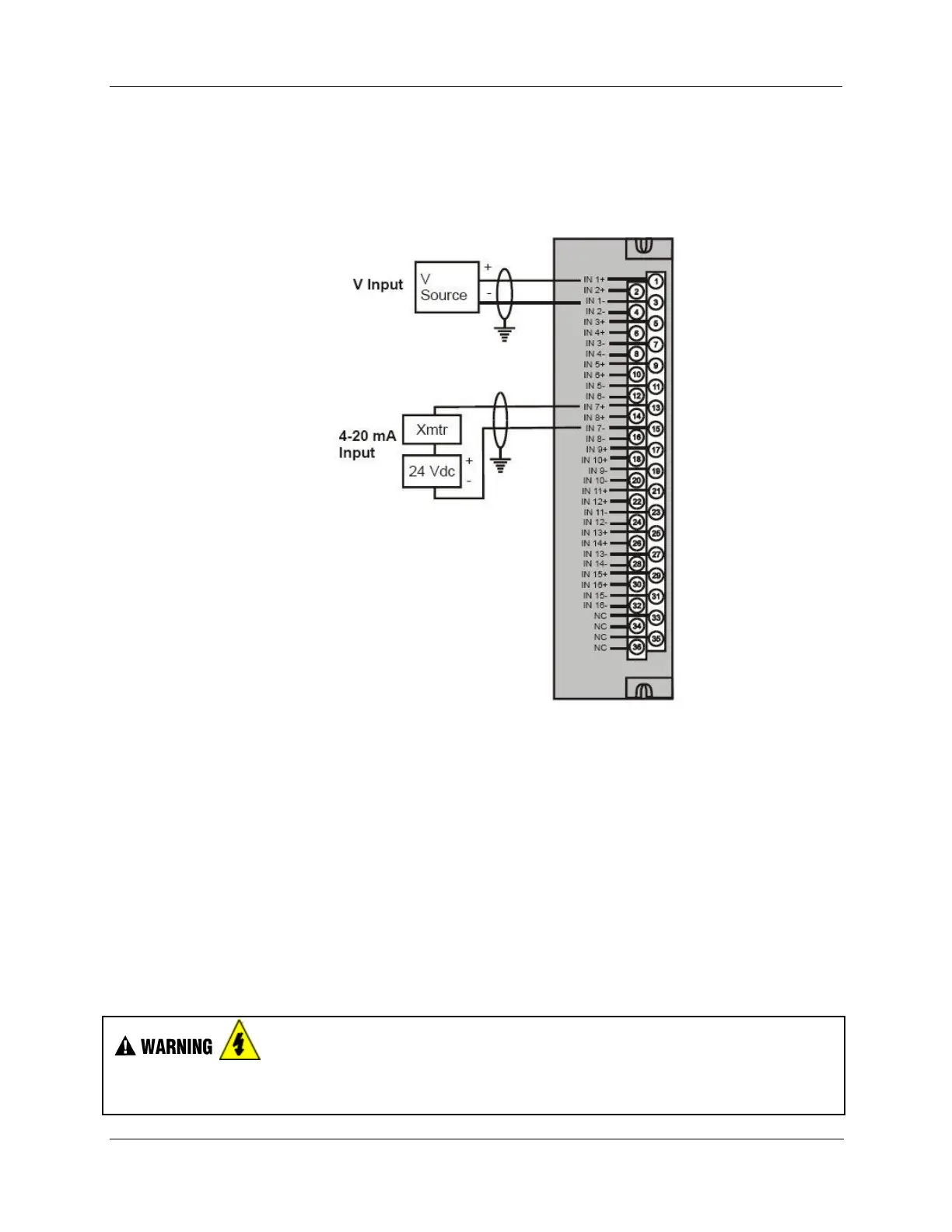
16 point High Level Analog Input Wiring (Figure 49)
Be sure to set the module DIP switches for voltage or current mode. See page 87. This requires Low
Voltage Euro style 36-terminal terminal block.
Note: Unused input channel shall not be left open for 900A16-0102 IO module
Figure 49 – 16 point High Level Analog Input Wiring
4 channel Analog Output Module Wiring
An example of Analog Output Module wiring is shown in Figure 50. Specifications for this module and for
other modules are given in the Specifications manual. SIL applications require an external series relay used
to ensure outputs achieve failsafe action. See HC900 Process & Safety Controller Safety Manual for
additional details.
Isolation
The four outputs are isolated from each other.
Shield Grounding
Shields must be grounded as described under Shield Grounding at the beginning of this section.
Hazardous voltages exist at terminal blocks.
Using switches at field devices disconnect the field wiring form power sources before servicing.

 Loading...


