Revision 6 HC900 Process & Safety Controller User and Installation Manual 63
21 April 2017
LOAD
+24VDC
DI
Sourcing
DO-32
900H32
DI-16
900G02
OR DI-32
900G32
Relay Output
900H01
LOAD
+24VDC
DI
Sinking DO-16
900H02
DI-16
900G02
OR DI-32
900G32
Relay Output
900H01
Note: DI Sense is inverted
LOAD
+24VDC
DI
Relay Output
900H01
Relay Output
900H01
DI-16
900G02
or DI-32
900G32
Note: DI Sense is inverted
LOAD
+24VDC
DI
Relay Output
900H01
Relay Output
900H01
DI-16
900G02
OR DI-32
900G32
9.5 V >= VALID HIGH <= 32.0 V
0.0 V >= VALID LOW <= 3.5 V
LOAD
DI
DO-8
900H03
DI-16
900G03
900G04
Relay Output
900H01
LOAD
DI
Relay Output
900H01
Relay Output
900H01
DI-16
900G03
900G04
Note:
DI Sense is inverted when Load is placed
on High side (relay sinks power).
DI Sense is NOT inverted when Load is
located on Low side ( relay sources power).
110/220
AC
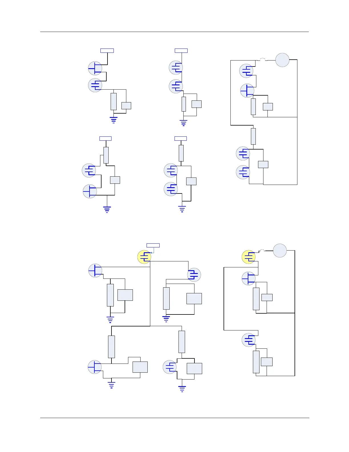
Figure 34 – Individual Series DO connections
LOAD
DI
Relay Output
900H01
DI-16
900G02
or DI-32
900G32
LOAD
DI
Sinking DO-16
900H02
DI-16
900G02
or DI-32
900G32
LOAD
+24VDC
DI
Sourcing
DO-32
900H32
DI-16
900G02
or DI-32
900G32
LOAD
DI
Relay Output
900H01
DI-16
900G02
or DI-32
900G32
9.5 V >= VALID HIGH <= 32.0 V
0.0 V >= VALID LOW <= 3.5 V
LOAD
DI
DO-8
900H03
DI-16
900G03
900G04
LOAD
DI
Relay Output
900H01
DI-16
900G03
900G04
110/220
AC
Note: DI Sense is inverted
75 VAC >= VALID HIGH <= 250 VAC
0.0 V >= VALID LOW <= 20 VAC
Note:
DI Sense is inverted when Load is placed
on High side (relay sinks power).
DI Sense is NOT inverted when Load is
located on Low side ( relay sources power).
Figure 35 – Common Series DO connections

 Loading...


