EasyManuals Logo

Honeywell HC900 User And Installation Manual

Honeywell HC900
274 pages
To Next Page IconTo Next Page
To Previous Page IconTo Previous Page
Page #76 background imageLoading...
Page #76 background image
62 HC900 Process & Safety Controller User and Installation Manual Revision 6
21 April 2017
Hardware and wiring requirements for safety configuration
For the function blocks for safety a special hardware configuration and wiring is required.
Below high level diagram explains the wiring concept for using the validation function blocks.
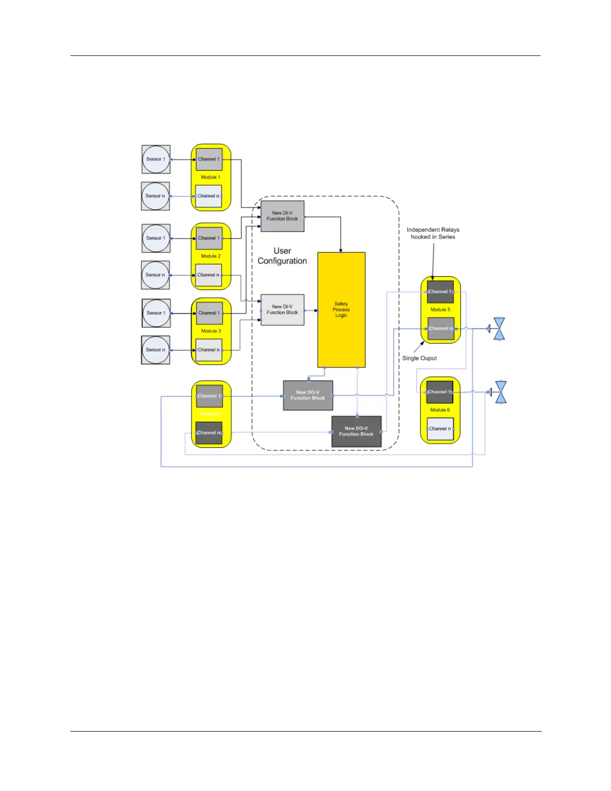
Figure 33 - IO-V function block connections
Figures 34, 35, and 36 demonstrate the connection of a series output relay’s normally OPEN contact to
protect against outputs that are stuck “ON”. This relay may be added individually as shown in Figure 34
and 36 or common for multiple channel outputs as shown in figure 35 and 36. The series output must be
configured to operate when the DO-V’s or AO-V’s Fail pin or VFail pin goes “ON”.

Table of Contents

Other manuals for Honeywell HC900

Questions and Answers:

Question and Answer IconNeed help?

Do you have a question about the Honeywell HC900 and is the answer not in the manual?

Honeywell HC900 Specifications

General IconGeneral
SeriesHC900
RedundancyOptional
Programming LanguageFunction Block Diagram, Ladder Logic, Structured Text
InputsAnalog, Digital
OutputsAnalog, Digital, Relay
DisplayOptional
ControlPID, Advanced Control
Power Supply24V DC or 100-240V AC
Storage Temperature-40°C to 85°C
Humidity5% to 95% non-condensing
Communication ProtocolsModbus, Ethernet

Related product manuals