34 HC900 Process & Safety Controller User and Installation Manual Revision 6
21 April 2017
.
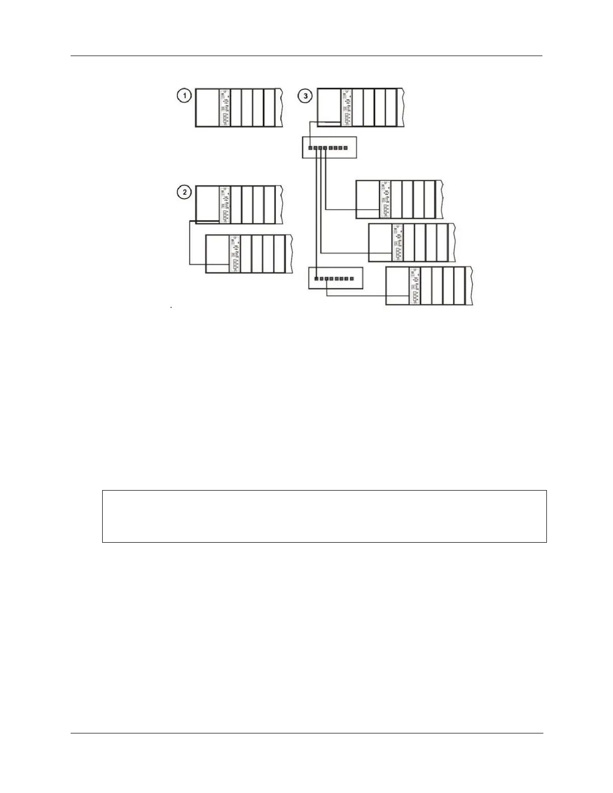
Figure 18 – HC900 Controller Configurations
In any of the racks shown in each controller configuration can be 4-, 8-, or 12-slot versions.
The Ethernet cables for the I/O expansion links are standard shielded Cat 5 cables, with standard RJ45
connectors. Each cable segment can be up to 100 meters (328 feet) long.
You can also use fiber optic cable for connections between the controller and a remote rack. Please refer to
HC900 specification document (51-52-03-31) for more details.
Configuration 1 is the C30/C30S/C50/C50S/C70/C70S CPU with I/O but no I/O expansion racks.
Configuration 2 shows the C50/C50S/C70/C70S CPU with 1 I/O expansion rack. The Ethernet cable
connects directly between the 10/100 Base-T connectors on the C50/C70 CPU Controller Module and the
Scanner Module.
ATTENTION:
For 2 or more I/O expansion racks a switch is required. Use only Honeywell recommended switches
(part no. 50008930-001, 50089785-001). The total number of switches is limited to 2 in series between
a CPU and its scanners.
Configuration 3 shows the C50/C50S/C70/C70S CPU with 3 I/O expansion racks. Since there are at least 2
I/O expansion racks a switch is required. When an Ethernet switch is used to connect to expansion I/O, a
cable goes between the I/O port on the controller to the switch. Two cables go from the switch to 2
scanners. A third cable goes from the switch to a second switch, which connects to a third remote scanner.

 Loading...


