EasyManuals Logo

Honeywell HC900 User And Installation Manual

Honeywell HC900
274 pages
To Next Page IconTo Next Page
To Previous Page IconTo Previous Page
Page #201 background imageLoading...
Page #201 background image
Revision 6 HC900 Process & Safety Controller User and Installation Manual 187
21 April 2017
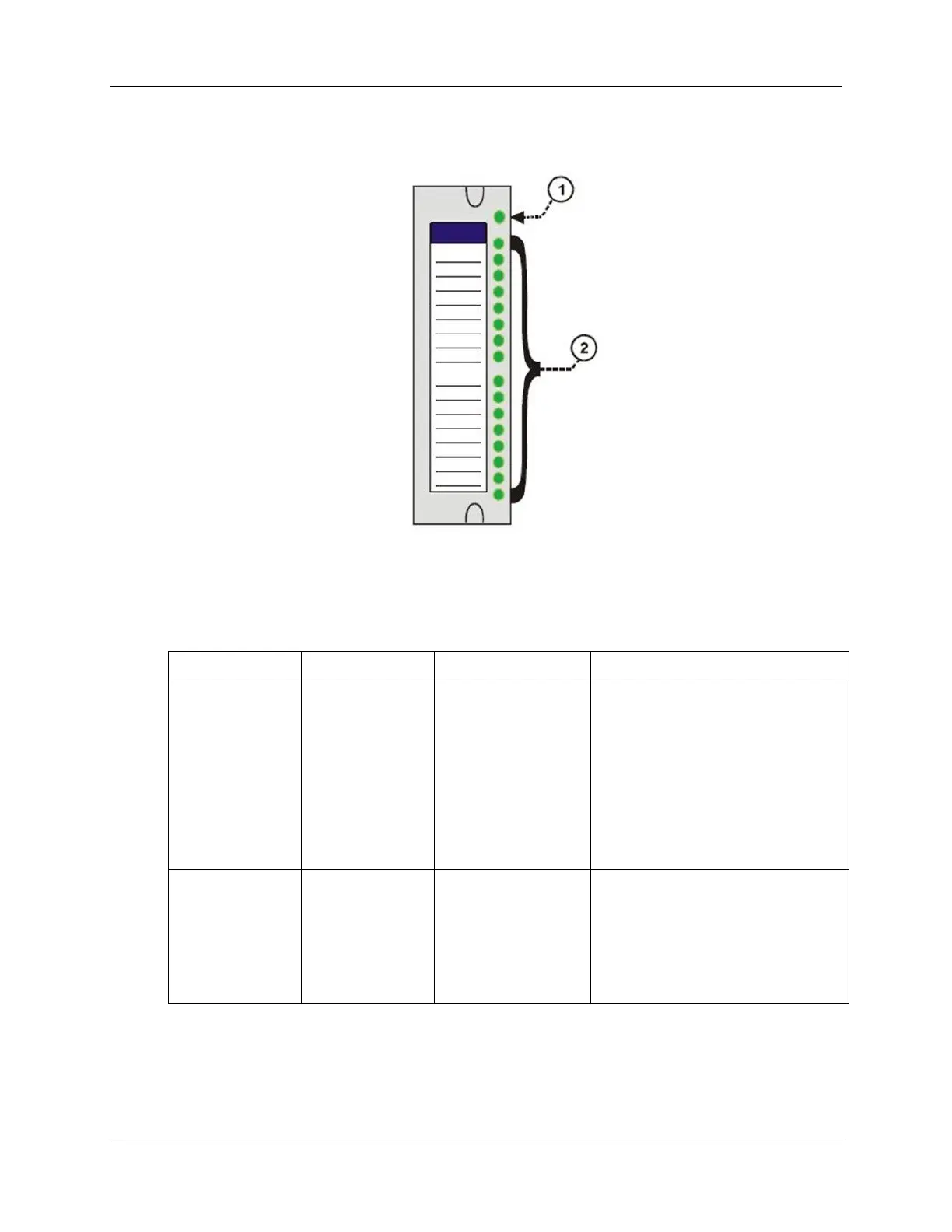
I/O Module Indicators
Figure 91 I/O Module LED indicators
Table 30 LED Indications on I/O Module
Figure 91 item
LED
LED State/Color
Description
1
Module Status
Off
Solid Red
Blinking Red
Blinking Yellow
Solid green
Blinking Green
No power.
Hardware failure
Diagnostic Code; refer to Table 31
I/O Module LED Diagnostics.
At least one output is Forced.
Cold start with passing diagnostics
Normal scanning
2
Channel LEDs
(one per input or
output)
Green (On/Off)
For Inputs, indicates On or Off status
of the field input even if Forced to the
opposite state.
For Outputs, indicates On or Off status
of the output including if Forced.

Table of Contents

Other manuals for Honeywell HC900

Questions and Answers:

Question and Answer IconNeed help?

Do you have a question about the Honeywell HC900 and is the answer not in the manual?

Honeywell HC900 Specifications

General IconGeneral
SeriesHC900
RedundancyOptional
Programming LanguageFunction Block Diagram, Ladder Logic, Structured Text
InputsAnalog, Digital
OutputsAnalog, Digital, Relay
DisplayOptional
ControlPID, Advanced Control
Power Supply24V DC or 100-240V AC
Storage Temperature-40°C to 85°C
Humidity5% to 95% non-condensing
Communication ProtocolsModbus, Ethernet

Related product manuals