ATTENTION: RTP and cables are intended for permanent installation within their own enclosure.
Mount RTP cable assembly to HC900 Controller (Figure 84).
Remove appropriate key tabs from terminal block to allow mating with the module. See page 85.
Connect desired cable to relay output module at controller. Choose from:
900RTC-H010 Remote Terminal High Voltage Cable assembly, 1.0 meters long
900RTC-H025 Remote Terminal High Voltage Cable assembly, 2.5 meters long
900RTC-H050 Remote Terminal High Voltage Cable assembly, 5.0 meters long
ATTENTION:
Cable power is limited to 24 Amps per module at 60C (140 degrees F) and 32 Amps at 54C
(129 degrees F).
Install relay output module label onto the module connector cover.
Connect shield drain wire to the grounding bars at the base of the HC900 rack. All field-wiring
shields must be grounded as described in the shield grounding section (page 81).
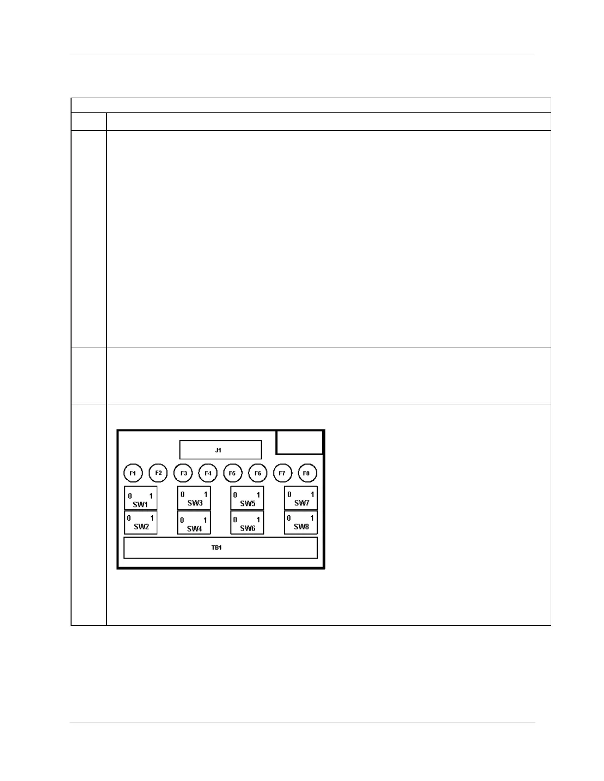
Module Removal / Insertion Under Power (RIUP) is supported by turning off all eight switches to allow
removal of the module from the rack without causing an arc. Please see page 83 for more details.
See page 227 for RTP internal schematic.

 Loading...


