EasyManuals Logo

Honeywell HC900 User And Installation Manual

Honeywell HC900
274 pages
To Next Page IconTo Next Page
To Previous Page IconTo Previous Page
Page #240 background imageLoading...
Page #240 background image
226 HC900 Process & Safety Controller User and Installation Manual Revision 6
21 April 2017
Relay Output
Step
Action
4
Connect field wiring.
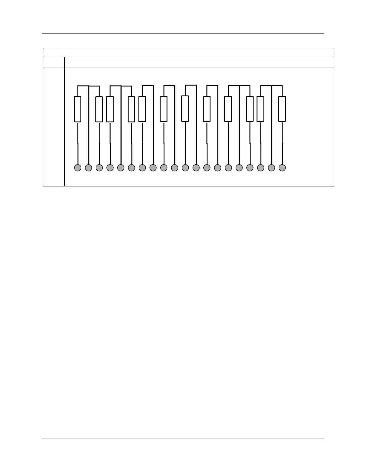
1 2 3 4 5 6 7 8 9 10 11 12 13 14 15 16 17 18 19 20
DO
-8
DO
-7
DO
-6
DO
-5
DO
-4
DO
-3
DO
-2
DO
-1
LOAD NO
LOAD NC
LOAD NO
LOAD NC
LOAD NO
LOAD NC
LOAD NO
LOAD NC
LOAD NO
LOAD NO
LOAD NO
LOAD NO
ATTENTION
Cable power is limited to 24 Amps per module at 60C (140 degrees F) and 32 Amps at 54C
(129 degrees F).
As shown in the schematic, each switch is SPST and opens and closes one lead of the relay
wiring. If your application requires opening and closing both sides of the load wiring, then an
external DPST switch is required.

Table of Contents

Other manuals for Honeywell HC900

Questions and Answers:

Question and Answer IconNeed help?

Do you have a question about the Honeywell HC900 and is the answer not in the manual?

Honeywell HC900 Specifications

General IconGeneral
SeriesHC900
RedundancyOptional
Programming LanguageFunction Block Diagram, Ladder Logic, Structured Text
InputsAnalog, Digital
OutputsAnalog, Digital, Relay
DisplayOptional
ControlPID, Advanced Control
Power Supply24V DC or 100-240V AC
Storage Temperature-40°C to 85°C
Humidity5% to 95% non-condensing
Communication ProtocolsModbus, Ethernet

Related product manuals