Revision 6 HC900 Process & Safety Controller User and Installation Manual 149
21 April 2017
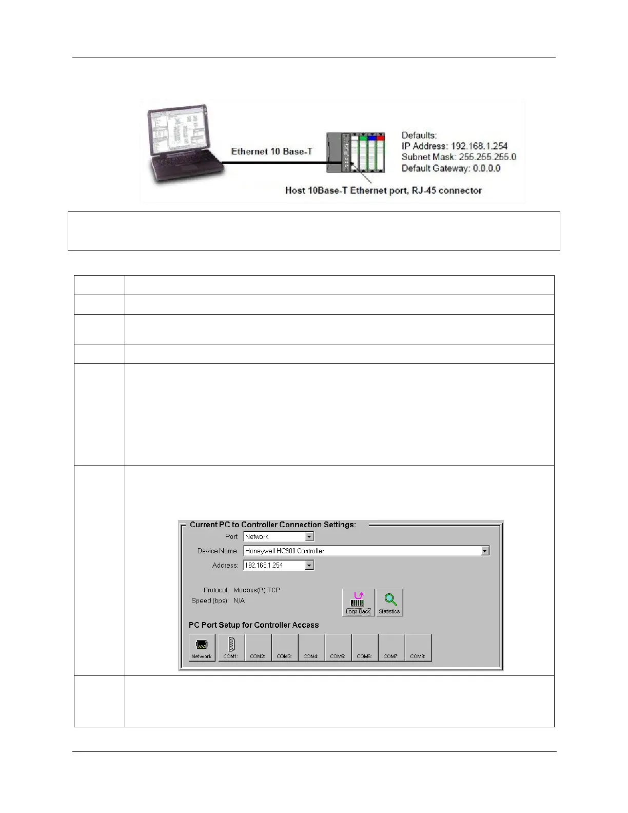
C. Direct Ethernet Connection to one HC900 controller
ATTENTION:
Always observe the wiring/cabling guidelines on page 54.
Make sure the PC has an Ethernet NIC (Network Interface Card) installed and enabled.
Connect an Ethernet 10/100 Base-T crossover cable to the HC900 controller’s Open Ethernet RJ-45
port (top RJ-45 port).
Connect the other end of the Ethernet 10/100 Base-T crossover cable to the PC’s network port.
On the PC, use the Utilities Worksheet in the Designer software to connect to the controller over
Ethernet. Every HC900 controller is shipped with the default IP address of 192.168.1.254 and Subnet
Mask of 255.255.255.0. You can use these network parameters initially for testing or configuration
use. In the Current PC to Controller Connection Settings area of the dialog box, click on the Network
button to bring up the Network Port Properties dialog box and Add the default IP address. Be sure the
Ethernet Network Interface Card in the PC has a fixed IP address on the same subnet as the
controller (192.168.1.x, where x= 2 to 253).
Note: 900 Control Station uses IP 192.168.1.253 as default.
In the Current PC to Controller Connection Settings area of the dialog box, select Network for the
Port to be used and the default IP address for the Address. Click on Loopback to assure
communications between the PC and the controller. You may now use the Ethernet port for
configuration interface.
Consult your IT systems administrator for allocating IP addresses if this controller will require a
unique IP address within a plant network. Also ensure that the PC Network Interface Card has an IP
address that allows access to the controller on the subnet after changing the controller’s network
parameters.

 Loading...


