Revision 6 HC900 Process & Safety Controller User and Installation Manual 75
21 April 2017
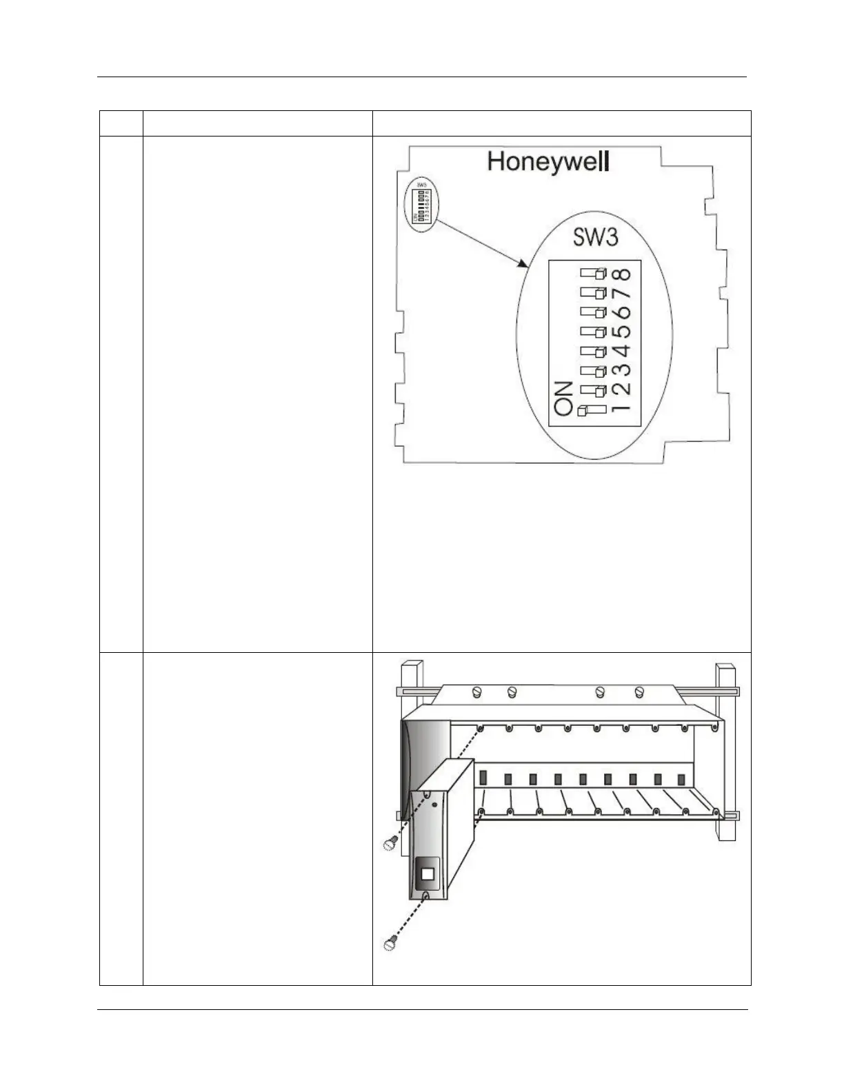
Set scanner address for the I/O rack
using the Scanner Module DIP
switches on SW3 (shown at right). For
C50/C70, use addresses 1-11. For
C75, use addresses 1-12.
Scheme 1 (upto 5 racks):
DIP switches 6-8 must be OFF. Only
one DIP switch may be ON:
DIP switch 1 ON = Scanner 1
DIP switch 2 ON = Scanner 2
DIP switch 3 ON = Scanner 3
DIP switch 4 ON = Scanner 4
DIP switch 5 ON = Scanner 5
Scheme 2 (upto 12 racks):
DIP switch 6 NO Always and
1 ON = Scanner 1
2 ON = Scanner 2
2 & 1 ON = Scanner 3
3 ON = Scanner 4
3 & 1 ON = Scanner 5
3 & 2 ON = Scanner 6
3 & 2 & 1 ON = Scanner 7
4 ON = Scanner 8
4 & 1 ON = Scanner 9
4 & 2 ON = Scanner 10
4 & 2 & 1 ON = Scanner 11
4 & 3 ON = Scanner 12
A small slotted screwdriver or
paperclip works well; avoid pencils.
Repeat steps 1 through 3 for each I/O
expansion rack.
Then, for each I/O expansion rack,
insert the Scanner Module
immediately to the right of the Power
Supply, and secure it in place with the
two captured screws in the faceplate.

 Loading...


