Chapter 5 – General Operation
Honeywell Confidential: Use or disclosure of information on this page is subject to the restrictions on the title page.
13841 Rev A
121
beam. During placement of the target on installation, it is easy to
turn the propeller so the pulsating reflecting light just goes out
after passing the beam of the photocell.
This point is the exact spot where alignment of the beam and the
retro- reflective target occurs electronically. A dry (erasable) ink
mark on the spinner and a a matching mark on the cowl, where
electronic alignment occurs, helps alignment of the target and
beam while the user is making balance adjustments.
5.4.3.3
Changing Performed Solutions
To change a solution to match any change that was actually
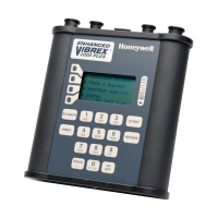
made (as opposed to a suggested change), use the numeric keys
to change the weight and clock angle when the Solution screen
displays.
For example, enter a weight change of 22.3 g by pressing the
keys 2, 2, 3 in that order. Enter a clock angle of 1:30 by pressing
0, 1, 3, 0 or 10:30 by pressing 1, 0, 3, 0 (in that order).
Once the user has applied the correct weight to the propeller,
press the START key (see below). To advance to the next run,
answer Yes to the question “IMPORTANT-were these
changes made?”.

 Loading...


