Chapter 6 – Maintenance
Honeywell Confidential: Use or disclosure of information on this page is subject to the restrictions on the title page.
13841 Rev A
232
6.3.7.1
Parts List
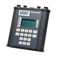
The following table lists the Vibrex 2000 and Vibrex 2000 Plus
parts called out in the procedures given in this chapter (and
related parts), including their names, part, and reference
numbers:
Chassis (housing/keypad assembly)
Screw, 4-40 by 3/8, Phillips, trilobular
Connector end plate, silk screened
MS (military standard) panel jack
No. 8-4S
Nut, 4-40, nylon lock standard
Screw, 4-40 by 3/8, Phillips
Standoff, 4-40, 1/2 in. nylon hex
MS panel connector No. 10-6S
Standoff, male/female, No. 4, by 1.75
Battery contact PCB assembly;
includes fuse (F1) and spring
Battery contact PCB assembly;
includes fuse (F1) and spring
Screw, 4-40 by 1/4, Phillips, black

 Loading...


