Chapter 6 – Maintenance
Honeywell Confidential: Use or disclosure of information on this page is subject to the restrictions on the title page.
13841 Rev A
213
touching the EPROM. These precautions make sure the electrical
potential of all parts is the same.
CAUTION: There is no risk of electrocution from the
Vibrex unit, but electrostatic discharge could damage the
EPROM chip.
Required Tools - The table below shows the tools required for
EPROM replacement.
No. 1 Phillips (cross-
head)
6.3.2.3
Replacement Procedures
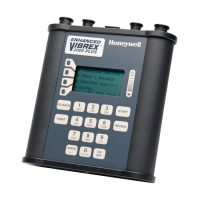
For a complete diagram of how to disassemble the Vibrex unit,
see Section 6.3.7 Complete Unit Disassembly (numbers in
parentheses refer to reference numbers in this diagram and in the
table in Section 6.3.7.1 Parts List).
Replace the EPROM chip, as follows:
1. Remove the battery end plate (15) that holds the
batteries in place, by turning the large Phillips screw
(16) counter-clockwise, using the No. 1 Phillips
screwdriver.
2. Remove the batteries (20).
3. Remove the four 4-40 (03) screws holding the shield to
the bottom of the chassis.

 Loading...


