Chapter 4 – Installation
Honeywell Confidential: Use or disclosure of information on this page is subject to the restrictions on the title page.
13841 Rev A
81
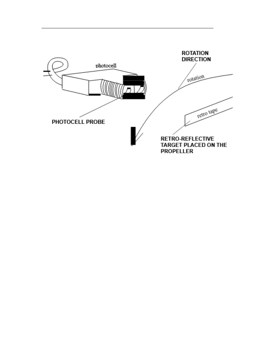
Check the small LED pulsating on the back of the photocell to
verify correct placement. A faster pulse rate of the alignment
indicator means better alignment. However, if the pulse rate is
too fast to observe, the user may need to reduce the length of the
retro-reflective target strip.
To calculate the best dwell time and length for the retro-
reflective target in the photocell beam, see the graph that shows
minimum target length, under “Appendix A: Photocell Taping”.
4.4.3 Magnetic Pickup
If the user needs instructions on magnetic pickup installation,
refer to the aircraft maintenance manual for the subject aircraft.
Refer to the appropriate Honeywell Model 177M-6A Vibrex
checklist for magnetic pickup installation, if other documentation
is inadequate. The installation for the Vibrex 2000 and Vibrex
2000 Plus is the same.

 Loading...