Chapter 4 - Installation
Honeywell Confidential: Use or disclosure of information on this page is subject to the restrictions on the title page.
13841 Rev A
80
is called incident light, that is, light hitting the assembly when
the target is not in line with the beam. For example, light
reflected from a shiny surface that enters the photocell probe is
incident light.
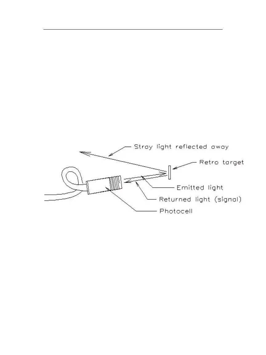
For the best results, mount the photocell probe so any incident
light is reflected away from the photocell’s beam (see the
diagram below). This position is especially necessary when the
target attaches to bright metal or glossy surfaces.
The illustration below shows an example of correct photocell
positioning for optimum retro-reflection.
4.4.2.5
Target Positioning
Rotate the component to be balanced to a position where a blade
or some easily identifiable part of the rotating assembly crosses
the photocell beam. Place a single retro-reflective target strip
aligned tangentially on the rotating component, where the target
is illuminated by the photocell’s beam.
Target Diagram - For details on this operation, see below.

 Loading...