Chapter 3 – Getting Started
Honeywell Confidential: Use or disclosure of information on this page is subject to the restrictions on the title page.
13841 Rev A
35
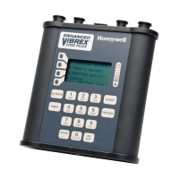
For example, selecting configuration 1A means the Vibrex unit
is using channels No. 1 and A. The channel names shown in the
previous table represent the following values:
Numbers refer to the Velocimeter (vibration) transducer
channel(s) the Vibrex unit is using and show values in IPS.
Letters refer to the photocell or magnetic pickup (azimuth)
channel(s) being used and show values in RPM.
Choosing a Channel Entry - As many times as necessary,
press the context key next to the screen display line that contains
the angle brackets, until the desired channel entry displays.
Additional Channels on Enhanced Vibrex 2000 Plus – this
unit also allows the selection of two additional channels using
optional multi-channel adaptor cable (part number 902-18701-
X). The table below shows the Enhanced Vibrex 2000 Plus units’
channel configuration choices.
Velocimeter No. 1
(902-18701-1)
Velocimeter No. 2
(902-18701-1)
Velocimeter No. 3
(902-18701-2)

 Loading...


