Chapter 4 - Installation
Honeywell Confidential: Use or disclosure of information on this page is subject to the restrictions on the title page.
13841 Rev A
72
subpanel at the top of the unit contains all the major installation
interfaces for input and output.
Channel Descriptions - The following table shows each
channel, identified by its appropriate label on the Vibrex unit,
along with a description of the channel’s identification and
general function.
Velocimeter channel No. 1
Velocimeter channel No. 2
Photocell or magnetic pickup channel A
Photocell or magnetic pickup channel B
Auxiliary output for a nine-pin RS-232
serial cable; for interfacing the unit with
a personal computer (PC), a printer, or
the Strobex
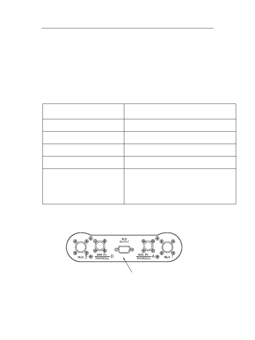
Connector Description - The diagram below shows an
illustration of the connector subpanel.
PC OR PRINTER INTERFACE OR
STROBEX SYNCHRONIZATION OUT PULSE

 Loading...