Model 5340A
Maintenance and Service
X
X
X
X
5
-
28. Connect the output of an HP Model 651A signal generator to the external trigger input of
an HP Model 222A pulse generator. Disconnect the harmonic frequency cable connected to
A16J2. Use suitable push
-
on to BNC (such
as
Sealectro 50
-
074
-
6800, HP P/N 1250
-
0831) and
connect the cable
to
the output of the pulse generator.
5
-
29. Set 651A frequency to
40
kHz
at
0.8V
rms
all zeros
some number
some number
all zeros
222A pulse polarity
to
+
222A rep rate to man/ext
+
222A pulse delay to
.1
222A pulse width to .03
-
.05
vernier to mid
-
position
222A pulse amplitude to
5
vernier to mid
-
position
5340A RANGE switch
to
250 MHz
-
18 GHz
5340A RESOLUTION switch to 10
K
X
X
X
X
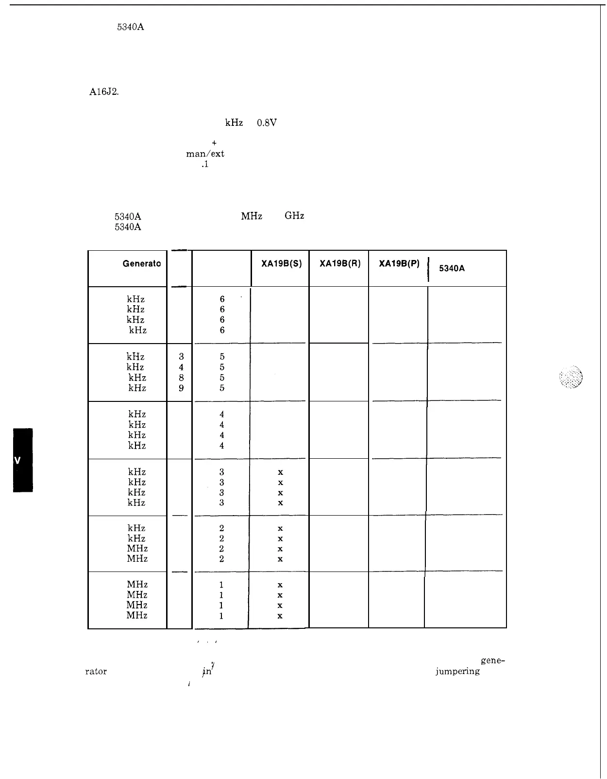
Signal Generato
Frequency
20 kHz
40 kHz
80 kHz
100 kHz
60 kHz
80 kHz
160 kHz
180 kHz
140 kHz
160 kHz
320 kHz
340 kHz
300 kHz
320 kHz
640 kHz
660 kHz
620 kHz
640 kHz
1.28 MHz
1.30 MHz
1.26 MHz
1.28 MHz
2.56 MHz
5.10 MHz
all zeros
some number
some number
all zeros
-
N
-
1
2
4
5
X
X
X
X
7
8
16
17
all zeros
some number
some number
all zeros
15
16
32
33
-
31
32
64
65
-
63
64
128
255
XA19B(S)
Binary 4
Range
No.
XA19B(R)
Binary
2
X
X
X
X
X
X
X
X
X
X
X
X
XAf9B(P)
1
5340A Display
Binary 1
-I
all
zeros
some number
some number
all zeros
-I
I
all zeros
some number
some number
all
zeros
I
1
all zeros
some number
some number
all zeros
I,
5
-
30.
In this test the various possible values of
N
will be simulated by varying the signal gene-
rator frequency
as
shown Pn the table below. The range will be simulated by jumpenng three
connections to chassis.
1
Note that there are
six
groups of four measurements. The first checks
that
N
is
outside the lower limit; the fourth checks that
N
is
outside the upper limit. The second
and third check that
N
is
within limits.
I
5
-
18