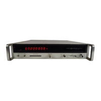
Model 5340A
Installation and Remote Programming
c.
Remove the two adhesive
-
backed trim
strips
MP1 from side frames MP3 and MP12.
d.
Using the three screws provided, attach the filler strip from the rack mount kit along the
front of bottom cover
MP9.
e. Attach the flanges from the rack mount kit to the front end of side frames MP3 and MP12.
Orient the larger corner notch toward the bottom of the instrument.
2
-
11. REPACKING
FOR
SHIPMENT
2
-
12. If it becomes necessary to reship a counter, good commercial packing should be used.
Contract packaging companies in many cities can provide dependable custom packaging on
short notice. Instruments should be packed securely in
a
strong corrugated container (350 lb/sq.
in bursting test) with suitable filler pads between the instrument and container. Before returning
instruments to Hewlett
-
Packard, contact the nearest Hewlett
-
Packard Sales and Service
Office for instructions.
2
-
13. ENVIRONMENT DURING STORAGE AND SHIPMENT
2
-
14. Conditions during
storage
and shipment should normally be limited
as
follows:
a. Maximum altitude: 25,000 feet.
b. Minimum temperature:
-40°F (-40OC).
c. Maximum temperature: +167’F (+75OC).
2
-
15. REMOTE PROGRAMMING AND DIGITAL OUTPUT
2
-
16. Option 011 adds remote programming and digital output capability to the 5340A Frequency
Counter. These are accomplished with
a
bi
-
directional bus, via
a
24
-
pin connector on the rear
panel marked DIGITAL
INPUT/OUTPUT. Associated with
this
connector are six slide switches
used to address the instrument.
A 5340A can be addressed to either send output data (TALK) or
to accept program information (LISTEN). For the purposes of the Option 011 description, several
terms are defined
as
follows:
a.
A TALKER
is
the sender of information on the bus.
b. A LISTENER
is
the receiver or acceptor of information on the bus.
c. A CONTROLLER
is
an instrument that has the responsibility of managing the instru
-
ments connected
to
the bus.
It
is
capable
of
addressing
other
instruments
on
the bus
as
TALKERS or as LISTENERS. It
is
a
TALKER and may be a LISTENER.
“High” or
‘‘0”
level of
a
line or switch
is
the relatively more positive signal level (22.4V).
“Low” or
“1”
level of
a
line or switch is the relatively less positive signal level (~0.4V).
d.
e.
2
-
17. What Can
Be
Programmed
2
-
18.
Also, the
5340A’s
octave range and
its
output mode can be selected. In addition,
a
controller can command the
5340A to make
a
measurement by sending either
a
SAMPLE TRIGGER or RESET instruction.
The controller can elect
40
give control to the front panel controls (LOCAL) or have the 5340A
operate according to ’the information stored in its remote program
storage
cells (REMOTE).
These are listed in Table
2-,kl
along with their associated codes.
2
-
19. When addressed
40
Ohput, the 5340A sends
a
string of
16
ASCII characters (USA Standard
Code for Information
fnterchange). It includes the measurement technique (direct or by using
phase locked loops), overflow, eight data digits (blank display digits are outputed as
0’s)
E
All front panel switch functions, except power, are programmable.
i
2
-
2

 Loading...