Model 5340A
Theory of Operation
Figure 4
-
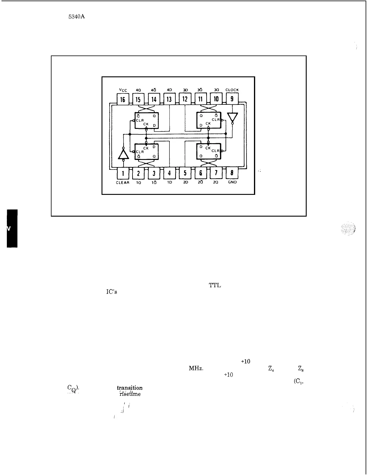
35. Quadruple D
-
Type Flip
-
Flops 1820
-
0839
4
-
81. Low Power 5
-
Bit Comparator 1820
-
0904
4
-
82. The 1820
-
0904 is a low power version of the 1820
-
0706.
4
-
83. Four
-
Bit Binary Full Adder 1820
-
0910
4
-
84. The 1820
-
0910 (Figure 4
-
36) uses low power Schottky
'ITL
circuits to achieve speeds com
-
parable to standard IC's
at
approximately one
-
fifth
of
the power. The adder performs the
addition
of
two 4
-
bit binary numbers. The sum
(C)
outputs are provided for each bit and the
resultant carry
(C4)
is obtained
from
the fourth bit. The operation of the adder is
shown
in the
truth table below.
4
-
85. EECL Bi
-
Quinary Counter 1820
-
1019
4
-
86. The 1820
-
1019 (Figure 4
-
37) consists of four EECL D
-
type flip
-
flops interconnected to
perform binary and quinary functions.
The quinary output
is
in
BCD code. The clock input of
the quinary may be connected to the
Z,
input of the binary to yield
a
el0 with
a
BCD output
code for direct readout of frequencies below 350
MHz.
For prescaling, the
Z,
or the
Z,
outputs may be connected to the clock input of the binary to give
a
110
output with
50%
duty cycle
on the binary output. Change of state occurs on the positive transition of the clock inputs
(C,,
C,,
or
CQ).
A
positive :ans,i$on
of
the reset input forces all outputs into the high state.
Maximum allowable clock
nsetkme
is
25
nanoseconds. The truth table below shows the count
sequence for BCD.
I,
,4
:i
I
4
-
26