Model
5340A
Theory of Operation
4
-
69. Synchronous Four
-
Bit Counter 1820
-
071 6
4
-
70.
This
IC (Figure
4
-
31)
is
a
high
-
speed, synchronous, presettable, four
-
bit binary counter
using an internal carry ahead circuit. The carry ahead circuitry provides for cascading counters
for n
-
bit synchronous configurations without additional gating. Synchronous operation
is
achieved by clocking
all
flip
-
flops simultaneously to change all outputs coincidently.
A
buffered
clock input triggers the four
J
-
K
master
-
slave flip
-
flops on the positive rising edge of the clock
input. The counters are programmable and maybe preset to either state. Since presetting
is
synchronous,
a
low on the load input (pin
9)
disables the counter and causes the outputs to agree
with the data inputs after the next clock pulse. The clear input is synchronous and a low level
at
the clear input sets all four of the flip
-
flops low
after
the next clock pulse. The carry look
-
ahead
function
is
accomplished with two count
-
enable inputs and
a
carry output. Both count
-
enable
inputs
(P
and T) must be high
to
count, and input
T
is
fed forward to enable the carry output.
When enabled, the carry output will produce a positive output pulse with a duration approxi
-
mately equal to the positive portion of the
QA
output.
This
positive overflow carry pulse can be
used to enable successive cascaded stages. High
-
to
-
low
-
level transitions
at
the enable
P
or
T
inputs should occur only when the clock input
is
high.
Figure
4
-
31.
Synchronous Four
-
Bit Counter
1820
-
0716
OUTPUlZ
CARRY
,---<
ENABLt
vcc
ouTPu1
oA
a0
oc
aD
T
LOAD
CLEAR CLOCU ENA0LE GND
UP
DATA
INPUTS
4
-
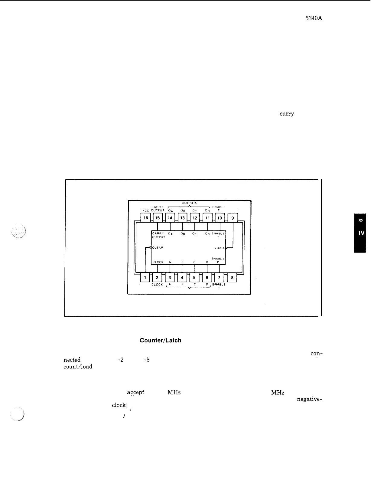
71. Presettable Decade Counter/Latch 1820
-
0751
4
-
72.
This
IC
(Figure
4
-
32)
consists of four dc
-
coupled, master
-
slave flip
-
flops internally cqn-
nected to provide
a
+2
and
a
+5
counter. The outputs may be preset to any state by driving the
count/load input (pin
1)
low and entering data at the data input lines. The outputs will follow the
inputs independent of the clock. The counter can also be used
as
four
-
bit latches by using pin
1
as
the strobe and entering data on the data inputs. In this mode, the outputs will follow the inputs
when pin
1
is low, but will remain unchanged (latched) when pin
1
is high and the clock
is
inactive. The counters aFcept
0
to
50
MHz
at
the clock
1
input and
0
to
25
MHz
at
the clock
2
input. During the count operation, transfer of information to the outputs occurs on the negative-
going edge of the clock: pulse. When the clear input
is
driven low, all outputs go low regardless
of the clock states.
i
I
4
-
23