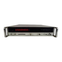
Model 5340A
Manual Changes and Options
7
-
9. OPTIONS
7
-
10. Options 001, 002, and 011 are available for the 5340A. Following
is
a
description of each
option.
7
-
11. Option 001 High
-
Stability Oscillator
7
-
12. Specifications for Option 001 are listed in Table
1
-
3.
This option consists of deleting the
standard oscillator assembly (05340
-
60036) and adding the following assemblies and parts:
a. A18
10544A oscillator assembly plugs into XA18 in place of the standard oscillator. The
b.
A33 Power Supply (plugs into
XA33).
The schematic diagram
is
shown in Figure 8
-
35
c. Transformer
T2. The schematic diagram is shown
in
Figures
8
-
33
through 8
-
35. The
schematic diagram
is.shown in Figure 8
-
24. The parts list
is
given in Table 6
-
3.
and the parts list is given in Table 6
-
3. Theory
is
contained
in
Section IV.
part number is listed in Table 6
-
3.
7
-
13. Option 002, Rear Panel Connectors
7
-
14. This option provides input connectors on the rear panel. Input
1
(10 Hz
-
18 Hz Type N
52)
is
installed on the rear panel in place of
J1
on the front panel. Input 2 (10 Hz
-
250 MHz BNC 58)
is installed on the rear panel in addition to 54 on the front panel. In addition,
a
50
-
ohm
termination is installed on the front panel BNC connector
54.
The termination reduces the input
impedance to 50
-
ohms. This ensures that the 5340A meets all specifications when Option
002
is
installed.
When the
5340A is equipped with this option, 10 Hz to 250 MHz direct count inputs
can be connected to either the rear panel
(58)
or the front panel connector (54). When the input
is
connected to the front panel input, the termination
is
removed and installed on the rear panel
BNC connector
J8. Parts for Option
002
are listed in Table 6
-
4. See Figures 8
-
2, 8
-
4, and 8
-
5 for
connector locations. The schematic diagram for the direct count input
is
shown in Figure 8
-
9.
The wiring for the rear panel N connector
is
the same
as
the front panel configuration, see Fig
-
ure 8-6.
7
-
15. Option 011, Remote Programming and Digital Output
7
-
16. Option 011 provides for remote programming and digital output. The digital output feature
requires additional accessory equipment to interface with HP printers, computers, and calculators
(see Table
1
-
2).
Also,
see Table 1
-
3 for specifications.
7
-
17. Option 011 consists of deleting assembly A19A and adding the parts listed in Table 6
-
5.
Schematic diagrams are given in Figure 8
-
26 and 8
-
36.
>
the assemblies associatedwith this option
is
given in Section IV
7
-
18. Operation and programming information is given in Section
11.
T eory of Operation for
i.
7
-
19. FIELD INSTALLATION
OF
OPTIONS
7
-
20. Installation
of
Option 001, High
-
Stability Oscillator
7
-
21. The following parts are required:
A18
5061
-
6cSj
A33 05340
-
60080,
2420-OOOf
05340-2Oq44
T2
9100-~0
9'
2360701
7
3050
-
0066
Qecillator Assembly
Oscillator Power Supply
Transformer
6
-
32 Snap Hex Nut
Oscillator Spacer
6
-
32
x
5/16 Pan Head Screw
with lock washers
Washer:Flat #6
1
ea.
1
ea.
1
ea.
2 ea.
2 ea.
2
ea.
2
ea.
7
-
16

 Loading...