Model 5340A
Manual Changes and Options
7
-
22.
To
install Option 001, refer to Figures 8
-
2 and 8
-
3 for instrument photos and Figures 8
-
24,
8
-
34, and 8
-
35 for schematics. Remove top and bottom covers and proceed
as
follows:
a. Remove A18 (05340
-
60036) and replace with High Stability Oscillator 10544A.
b.
On bottom of chassis, secure
10544A
as
follows:
(1)
Place oscillator spacers over oscillator studs protruding through chassis.
(2)
Using lockwashers, fasten the two 6
-
32
x
5/16 screws to the oscillator studs.
c. Install transformer
T2 into holes provided. Attach with 6
-
32 hex snapnuts.
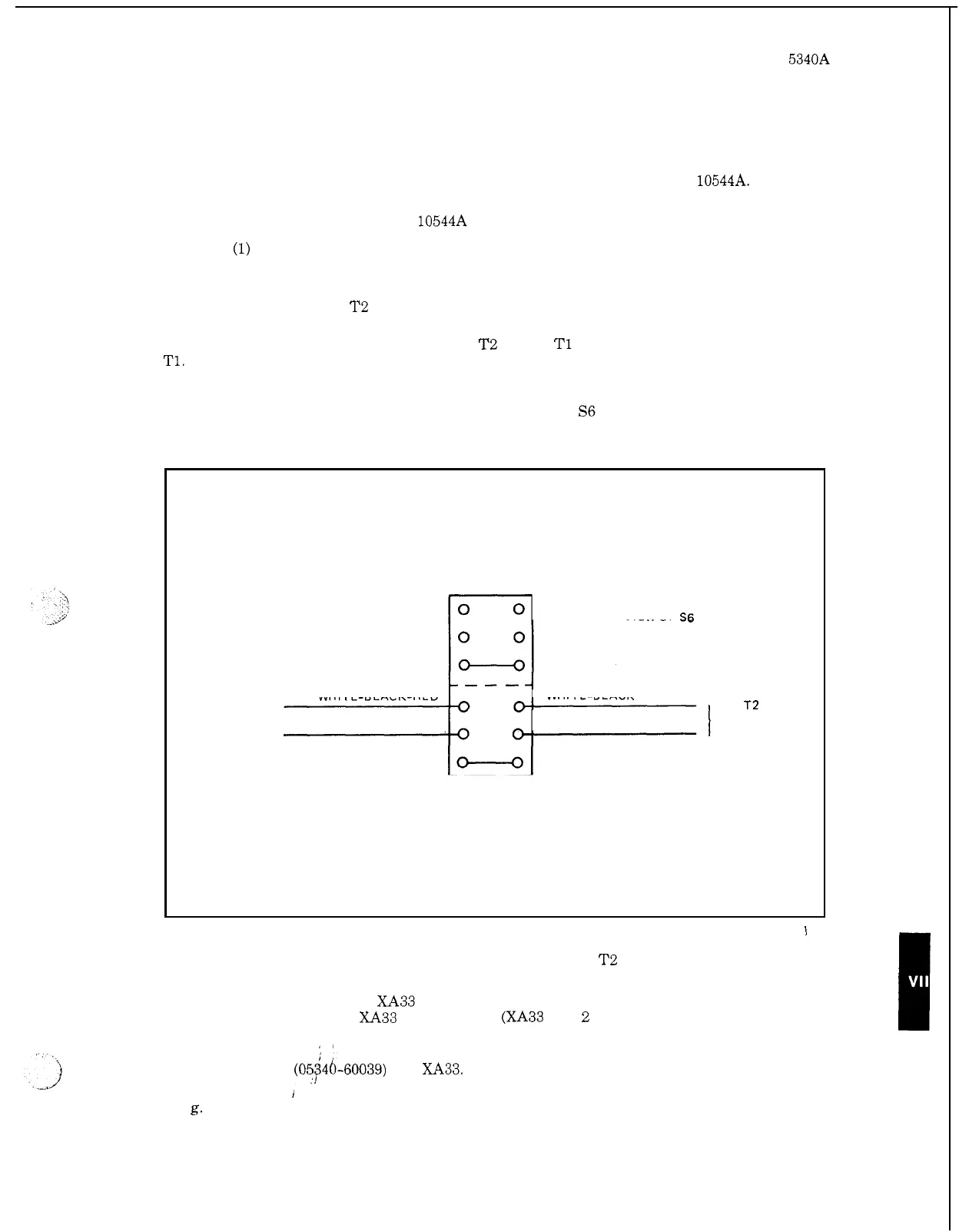
d. Dress the group of striped wires from
T2 toward T1 and through the cable clamp next to
T1. Continue to dress the wires between the power supply motherboard A30 (05340
-
60029) and
the left side frame and then toward the rear of the chassis. Route the striped wires through the
hole nearest to the left side frame. (The hole next to the fan will have
no
wires running through
it.) Cut, dress, and strip the striped wires and solder them to
S6
as
shown below. See Figures 8
-
34
and 8
-
35 for schematic diagrams.
TO
T2
SEE FIGURES
8
-
34
AND
8
-
35
TOP
SELECTOR
S6
VIEW OF
S6
TERMINALS
WHITE
-
BLACK
TO
T2
SEE FIGURES
I
8
-
34
AND
8
-
35
WHITE
-
BLACK
-
RED
WHITE
-
BLACK
-
YELLOW
,
WHITE
-
BLACK
-
GREEN
e.
Cut, dress, strip, and solder the solid colored wires from
T2
as
follows:
Orange wire (either one) to XA33 pin
3.
Other orange wire to XA33 pin
4.
Both blue wires to XA33 pins
2
and
B.
(XA33 pins
2
and B are already connected to
chassis through
a
black wire.)
'1
f.
Install
A33
(05446-60039) into
XA33.
g.
Apply ac power to counter and note that the
*
annunciator lights. The
*
should remain
lit for approximately
20
minutes. Adjust power supply A33
as
described in Table 5
-
3 step lg.
Adjust oscillator as described in Table 5
-
3, step 10.
I
7
-
17