Model 5340A
Theory of Operation
4
-
23. Four
-
Line to Ten
-
Line Decoder 1820
-
021 4
4
-
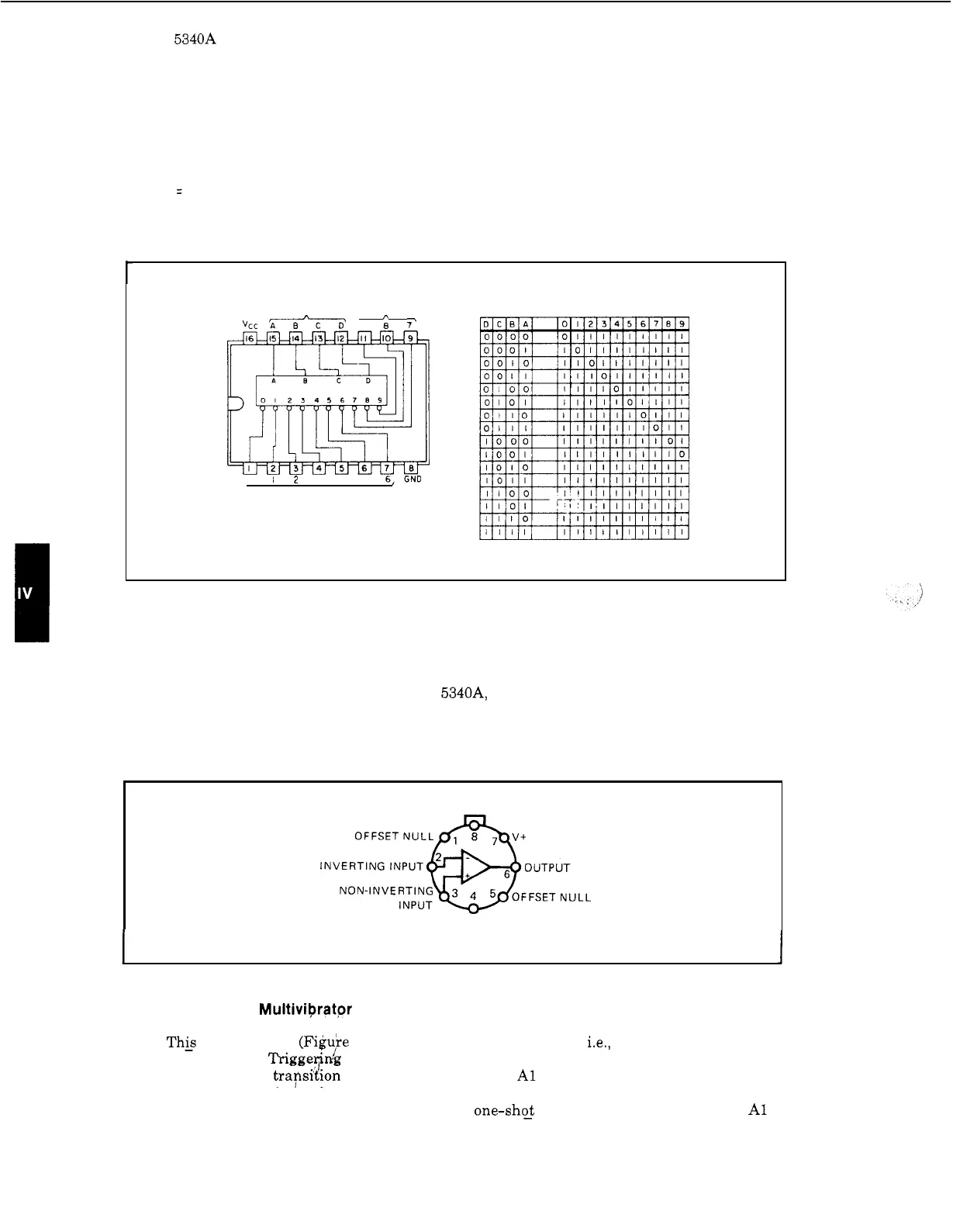
24. The 1820
-
0214 decoder (Figure 4
-
9) consists of eight inverters and
10
four
-
input NAND
gates. As shown in the truth table, the unit accepts BCD inputs and provides the equivalent
decimal output.
The activiated output will be
a
logic low. For example, if the BCD input
is
DCBA
=
0111, then the decimal 7 output will go low and all others will be high.
Figure 4
-
9. Four
-
Line to Ten
-
Line Decoder 1820
-
0214
r
INPUTS OUTPUTS
vcc
ITtf-TT
‘9
:
i
0
12
3
4
5
6,GND
OUTPUTS
1820
-
0214
(POSITIVE
LOGIC)
FOUR
-
LINE
TO
TEN
-
LINE DECODER
TRUTH TABLE
BCD INPUT DECIMAL OUTPUT
4
-
25. Operational Amplifier 1820
-
0216
4
-
26.
Figure
4
-
10
shows the diagram for the operational amplifier. Operational amplifiers are
so
named because they perform a mathematical operation in
a
circuit. The type of operation
is
determined by the feedback network. In the 5340A, this IC
is
used in
a
dc stabilizing feedback
network on A17.
Figure 4
-
10. Operational Amplifier 1820
-
0216
1
.
NOTE:
Pin
4
connected
to
case
I
4
-
27.
Monostable Multiviprator 1820
-
0261
4
-
27. This multivibrator (Fi$uie
4
-
11)
is stable in one state only; i.e., when not triggered,
Q
is
low and
Q
is high. Triggerink
is
dc from either positive or negative
-
going inputs and
is
not
directly related to the
transidion time of the input pulse.
A1
and A2 are negative
-
edge
-
triggered
logic inputs and will trigger the one
-
shot when either or both go low provided that B
is
high.
B
is
the positive Schmitt trigger input that triggers the
one-sh$ when
B
goes high with either A1 or
A2 low. When the monostable triggers,
Q
goes high and
Q
goes low for
a
period determined by
4
-
8