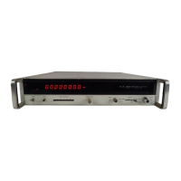
Model 5340A
Theory
of
Operation
4
-
103. SIMPLIFIED BLOCK DIAGRAM DESCRIPTION
4
-
104. Figure 4
-
45 illustrates the simplified block diagram for the 5340A Frequency Counter.
The counter has five major functional circuit groups; the input
-
phase lock loop, the transfer
phase lock loop, the
N
determination circuits, the counter circuits, and the interface circuits.
4
-
105.
Two separate inputs are provided for frequency measurements: the high impedance
-
low
frequency (10
Hz
-
250
MHz)
input, and the
10
Hz
to 18
GHz
input. The high
Z
input provides
a
direct comt path with high input impedance. The
10
Hz
to 18
GHz
input path either counts
directly from
10
Hz
to
-
225
MHz
or uses
a
transfer oscillator technique to count from
-
225
MHz
to
18
GHz.
Two phase lock loops are used in the transfer oscillator to down convert the input fre
-
quency to
a
countable range.
4
-
106.
F,
represents frequencies to be counted from 10
Hz
to 18
GHz.
The counter program
first
disp bles the transfer oscillator circuits while the counter “looks” for
a
direct count input
from
10
Hz
to
-
225
MHz.
If there is an input signal between
10
Hz
and
-
225
MHz,
the counter
establishes a direct count path. Signal flow
is
through the power divider and sampler (inactive)
to the counter circuits.
Whkn a direct count path is established, the phase lock loops are kept
inactive. If a direct count is not established within approximately
10
milliseconds, the transfer
oscillator circuits are activated and the input phase lock loop searches for the presence of signals
between
-
225
MHz
and
18
GHz.
If two or more signals are encountered, the phase lock loop
acquires the signal with the larger amplitude.
4-107. When the input phase lock loop locks on
a
signal,
it
provides an output frequency
F1
which is harmonically related to the value of
F,
as
follows:
N
is an
integer equal to the harmonic relationship between
F,
and
F1.
F,
=
NF1
-
20
MHz.
I
4
-
108. When the input phase lock loop locks, the transfer phase lock loop locks to provide a fre
-
quency output from the
N
determination circuits which
is
proportional to
N.
Since
F,
=
NF1
-
20
MHz,
the counter has the necessary information to calculate and display the value of
F,.
4
-
109.
The interface board for the standard instrument provides the control signals required
for completing and displaying a measurement. The interface board for Option
011
provides for
digital output data and remote programming in addition to supplying control signals.
i
4
-
110. OVERALL
THEORY
OF
OPERATION
4
-
111.
See Figure 8-6.
The overall block diagram for the 5340A
is
located in Section VIII on
a
foldout sheet.
4
-
112.
Input Circuits
‘
‘,
4
-
113. Two separate input pabhs are used: a high impedance direct count path
(10
Hz
to 250
MHz)
via input amplifier A3, and dl0
Hz
to 18
GHz
path through power divider
CP1,
A1 and A2. When the
input frequency to
CPl is’between
10
Hz
and 250
MHz,
a
direct count path is used consisting of
CP1,
A2A1, A2FL1, A17, and the counter circuits A18 through A26. For frequencies into CP1 above 250
MHz,
the transfer oscillator technique is used.
4
-
32

 Loading...