Model
5340A
Theory of Operation
SAMPLING
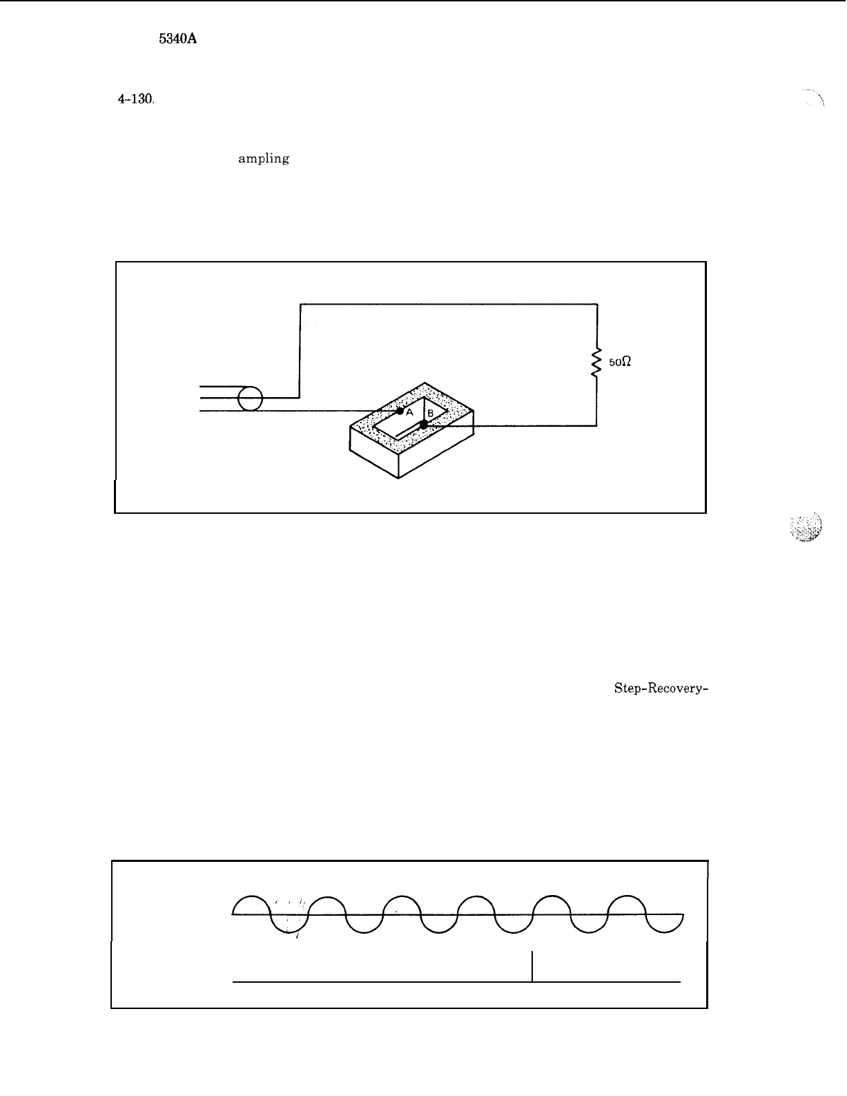
4-130.
A means must be provided to turn on the diodes periodically and this
is
achieved by
biasing the diodes into conduction by
a
sampler driver. Assume that
a
positive pulse
is
injected
into point A and a negative pulse into point
B
by the generators. The diodes are normally self
-
back
biased and are gated in a balanced fashion such that
a
low impedance path is provided through
the diodes and the
ampling capacitors to ground. The sampling capacitors charge towards the
voltage appearing at the input. To achieve high frequency response, it
is
necessary to turn the
diodes on for a very short time (typically
40
ps). Two hot carrier diodes are used because of their
extremely fast switching characteristics. The pulses required to turn on the diodes are developed
by inducing a traveling wave in
a
slot
as
shown in Figure
4
-
48.
Figure
4
-
48.
Sampler Slot
and negative pulses needed to turn on the diodes in Figure
4
-
47.
The two capacitors in Figure
4
-
47
connect to points A and
B
in Figure
4
-
48.
4
-
132. Sampler Driver
4
-
133.
transitions.
Diode
(SRD)
through
an
inductor, yielding extremely sharp spikes.
each cycle
of
the Voltage Controlled Oscillator (VCO) output.
The sampler driver output
is
differentiated by the slot in the sampler to provide fast
These are obtained from
a
Schmitt trigger circuit that drives
a
Step-Recovery-
One spike is supplied for
4
-
134. When Sampling Occurs
4
-
135.
The time and rate of sampling
is
carefully controlled by feedback in the phase lock loop.
In
a
DC phase lock loop (a method NOT used in this counter) the sampling rate
is
adjusted
for
a
constant sampler output.
,
Figure
4
-
49.
Sampling Timing
1
INPUT SIGNAL
4
-
36