Model 5340A
Theory of Operation
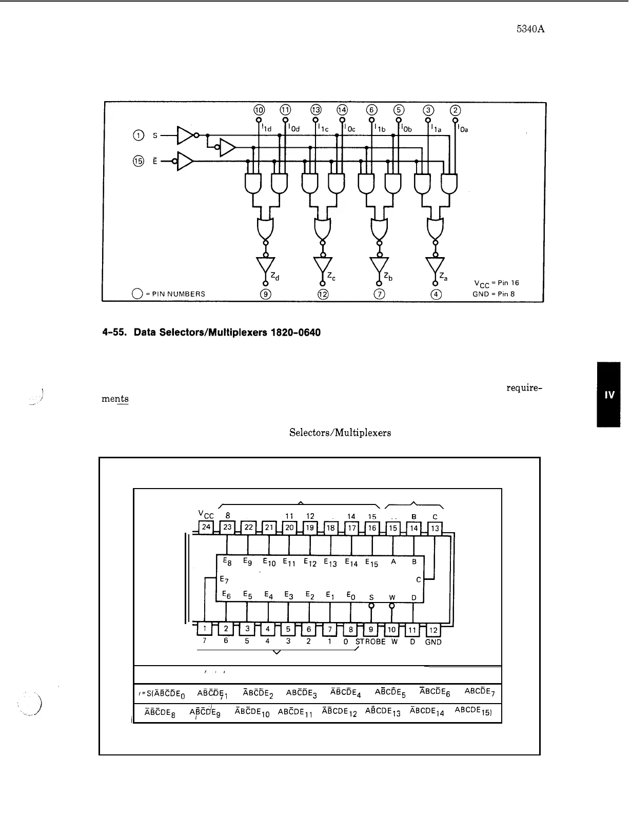
Figure 4
-
24. Quad 2
-
Input Multiplexer 1820
-
0616
I
4
-
56. This
IC
(Figure 4
-
25) selects
1
of 16 data sources and can be used for parallel
-
to
-
serial
conversion, multiplexing, or
as
a
five
-
variable function generator. Four data select lines are used
to select which input
is
routed to the output. The select lines perform binary decoding. When the
strobe input
is
driven low, the multiplexers are enabled. The truth table shows the logic require-
men? of the multiplexers. For example, when the strobe
is
low, and the data select lines are
ABCD,
then input
E3
is
gated to the output
W
line.
Figure 4
-
25. Data Selectors/Multiplexers 1820
-
0640
DATA INPUTS DATA SELECT
/
A
\-
"CC
8
9
10
11
12
13
14
15
A
R
c
\
v
/
OUT
-
DATA
DATA INPUTS PUT SELECT
~
POSITIVE LOGIC
,I
,=S(ABCDE~
+
ABCE~~
+
ABCDE~
+
ABCDE~
+
ABcEE,
+
ABCDE~
+
ABCDE,
+
ABCDE,
XBCDE,
+
A,@cD'E,
+
ABCDE,~
+
ABCDE,,
+
fiBCDEIZ
+
ABCDE13
+
ABCDE14
+
ABCDE15)
4
-
17