Model 5340A
Theory of Operation
4
-
51. Eight
-
lnput Multiplexer 1820-0615
4
-
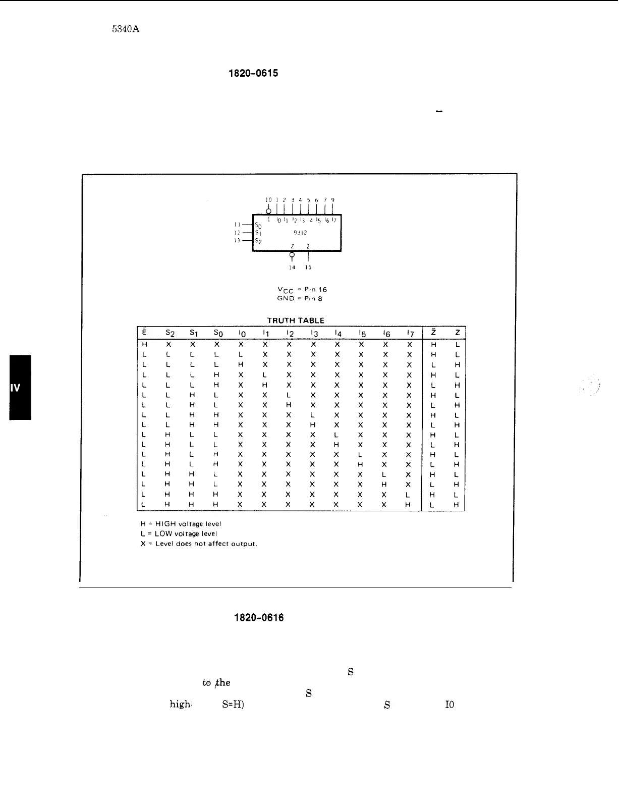
52. The 1820
-
0615 (Figure 4
-
23) selects one
-
bit of output data from eight inputs. The unit has
complementary outputs, and an enable input (low activates the multiplexer).
-
With the enable
line inactive, the multiplexer output
(Z)
is
low and the complementary output (Z)
is
high regard
-
less of the input states. The logic operation
is
shown in the truth table.
Figure 4
-
23. Eight
-
Input Multiplexer 1820
-
0615
4
-
53. Quad 2
-
Input Multiplexer 1820-0616
4
-
54. The 1820
-
0616 (Figure 4
-
24) consists of four 2
-
input multiplexers with common input
select logic, common active low enable and active high outputs. This allows four bits of data to be
switched in parallel to the’appsopriate outputs from four 2
-
bit data sources. When the enable
input is high (inactive), all outputs are held low. When the
S
input
is
high, the Ila, Ilb, Ilc, and
Ild inputs are transferred
t6 $he Za, Zb, Zc, and Zd outputs respectively. The transfer takes
place without polarity inversion. For example, if
S
is
high and
Ila
is
low, then
Za
will be low,
conversely if Ila
is
high1 (with
S=H)
then
Za
will go high. When
S
is low, the I0 outputs will
appear
at
the
Z
outputs.
4
-
16