Model
5340A
Theory
of
Operation
Figure
4
-
4.
Decade Counter
1820
-
0055
INPUT TRUTH TABLES
BCD COUNT SEQUENCE RESET
/COUNT
(SEE NOTE 2)
A
NC
ZA
ZD
GND
ZB
'ZC
(SEE NOTE
I)
RO(ll
'O(21
NC
"CC
'9(l)
R9(2)
INPUT
1820-0055(SN7490N)
2.
X
INDICATES THAT EITHER
A LOGICAL
I
OR
A LOGICAL
0
MAY BE PRESENT
DECADE COUNTER
4
-
15.
J
-
K
Flip
-
Flop
1820
-
0065
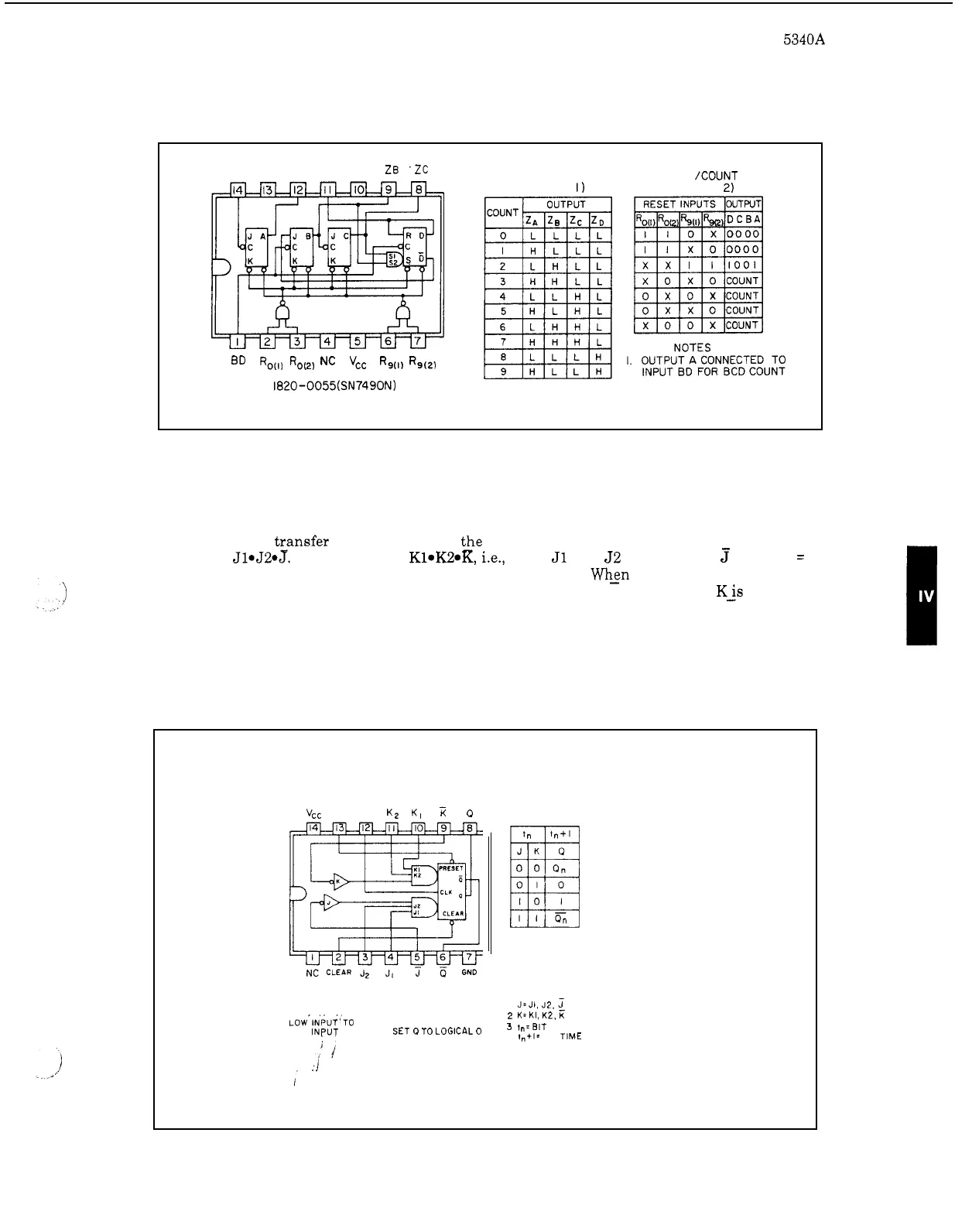
4
-
16.
Figure
4
-
5
shows the logic diagram, outline drawing, and truth table for the
1820
-
0065
J
-
K
flip
-
flop. The flip
-
flop
is
an edge
-
triggered type having direct clear and preset inputs. Input
information will
tzansfer to the outputs on t_he positive edge
of
the clock pulse. The
J
input
is
defined
as
51.52.5.
The
K
input
is
Kl.K2*K,
i.e., when
J1
and
52
are high and
3
is low,
J
=
1.
When
J
and
K
are both low, the clock pulses have no effect. Whsn
J
is
high and
K
is
low, the
positive clock transition will set the flip
-
flop
so
that
Q
is
high and
Q
is
low. When
Kis
high and
J
is low, the positive clock transition
will
reset the flip
-
flop
so
that
Q
is low and
Q
is
high. If
both
J
and
K
are high, the flip
-
flop will change states (toggle) with each positive clock transition.
A
low input
at
pin
13
will set the flip
-
flop and
a
low input to pin
2
will reset the flip
-
flop. The
clock must be at logic
0
before set or reset pulses are applied.
Figure
4
-
5. J
-
K
Flip
-
Flop
1820
-
0065
-
vCC
PRESET
CLK
K2
KI
J
-
K FLIP
-
FLOP
,
,
POSITIVE LOGIC
TRUTH TABLE
NOTE
CLOCK MUST BE AT LOGICAL
0
PRIOR TO THE APPLICATION OF
PRESET
OR
CLEAR FUNCTIONS
NOTES
I
J=JI.
J2.
1
2
K=KI, K2,
4
,"+I=
BIT
TIME
AFTER CLOCK PULSE
LOW'INPUT'TO
PRESET
SETS
o
TO
LOGICAL
I
3
tn=BI~
TIME
BEFORE
CLOCK
PULSE
LOW INPUT
TO
CLEAR SET
P
TO LOGICAL
0
i
4
-
5