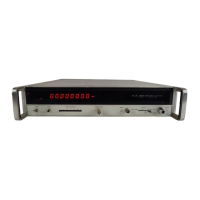
Model 5340A
Theory of Operation
into A23U20. Using range information and the resolution switch setting, A19 determines when
the “2” must be inserted
as
the eight columns of BCD information are shifted into A24.
4
-
254. U21A and U21B are activated for addition and U18D
is
used for subtraction.
The carry
information from
U19B
is
sent into the carry input of the first BCD adder U10. UlA, UlB, and
U12 determine when overflow occurs and activate flip
-
flop U19A to turn on the overflow light.
U17A and U17B turn on the lock and direct annunciator lamps
as
determined by circuits on A21.
U11
is
a
binary to BCD converter.
4
-
255. A24 DISPLAY REGISTER ASSEMBLY, 05340
-
60019
4
-
256. This Display Register (Figure 8
-
31) accepts and stores information to be displayed on the
display tubes and the annunciator lights.
4
-
257. U4 receives BCD inputs (weighted
8,
4, 2, and
1)
from A23 and supplies outputs to Ull,
U17, U9, and U16. U3, UlOB, and U3B detect zeroes and store a
TTL
high in U1 whenever a zero
is
detected. U2 determines how many insignificant (leading) zeroes exist and outputs a binary
code. U18
is
a
binary to decimal converter that receives the resolution switch information and
determines proper positioning
of
the decimal point. This information
is
coupled with leading
zero information to activate the appropriate blanking circuitry on A25. When shifting is com
-
plete, the BCD
“1”
information
is
stored in U16, with the Q8 output holding the
loo
information
and the
Q1 output holding the
108
information. Similarly U9, U17, and U11 contain the BCD
“Z”,
“4”, and “8” information, respectively.
4
-
258. A25 DISPLAY ASSEMBLY, 05340
-
60020
4
-
259. The Display Assembly (Figure 8
-
32) consists
of
display tubes DS1 through DS8, display
tube drivers
U1 through U8, decimal decoder U9, units decoder U10, units indicators DS15-17,
annunciators DS9 through DS14, and annunciator drivers Q1 through Q6.
4
-
260. The display tube drivers U1 through U8 are four
-
line BCD to decimal decoders. The table
below shows the decoder truth table.
I
4
-
261. When
a
particular output line of
a
decoder
is
on, the line is low to allow the corresponding
digit on the display tube to light. As an example of operation, assume that U8 receives a BCD
input of
D
=
L, C
=
H, B
=
L, and A
=
H. In this case, decoder U8 drives the 5 output low to light
the 5 digit in
DS8, the
loo
display tube. The anodes of the 100, 101, and 102 display tubes receive
+175 volts from the power supply through R5, R7, and R9. The remaining anodes are connected
to
the
blanking board
A26.
4
-
262. The decimal point decoder U9 receives four
-
line BCD from A24 and drives the left
decimal point in the display tube. The decimal point decoding
is
not proportional, for example,
when the BCD input is LLLL, the
0
output of U9 goes low to light the left decimal point in the
lo3
display tube. The theory of operation for the BCD decoding
is
described in the theory for A24.
To determine the required BCD input for
a
particular decimal point, the schematic (Figure 8
-
32)
and truth table can be
used.
For example, to light the decimal point in the 105 display tube,,
U9(13) (decimal 4) should go low which requires
a
DCBA input of LHLL.
4
-
263. The units decoder U10 is similar to the decimal point decoder U9. The GHz indicator will
light when the BCD input
is
equivalent to either
0,
3, 4, or 9. Similarly, the MHz indicator is
driven by the
1
or 7 output of U10. When the BCD input to U10 is equivalent to decimal 5, the
kHz light will light. For the theory of operation for this BCD input, refer to the description for A24.
4
-
264. The annunciators
DS9
through DS14 are controlled by inputs from A24. Emitter follower
Q7 and voltage divider R24
kind R25 establish
a
+2 volt bias for Q1 through Q6 and also for the
blanking board. As an example of operation, when system lock occurs, A24 supplies
a
low to the
emitter of Q2 to allow
&2 to conduct and light DS10. Zender diode CRl drops the 175 volts by ap
-
proximately 25 volts to operate DS9 through DS17.
4
-
50

 Loading...