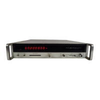
Model 5340A
Theory of Operation
4
-
146. Q1B
is
a
current source for Q1A to maintain the proper DC level for the input to U1.
Varying R10 changes the DC level on the drain of Q1B. Q1A is
a
unity gain amplifier that
presents
a
high input impedance to 54. To compensate for the loss of Q1A transconductance at
high frequencies and to keep the gain constant, C6 and R6 shunt high frequencies past
QlA.
4
-
147.
U1
is
used
as
an RF to EECL converter. A reference voltage
is
maintained on
U1
pin 8 and
the RF input signal is applied to pin 2. When pin
2
is
more positive than pin 8, the output on pin
4
will be logic high (EECL logic levels).
A complementary output on
U1
pin
5
is
detected by CR9
-
C15 and CRlO 416 to give automatic base line shift to compensate for the shift due to a non
-
symmetrical input signal (such
as
a
pulse train). When the output goes negative for more than
a
50% duty cycle, Q2 will turn on, forming
a
divider network of R17 and R12 with the +15V supply.
This raises the reference voltage at
Ul(8) by half the hysteresis of the circuit to increase the
sensitivity to
a
positive pulse train.
4
-
148. When Option 002
is
installed,
a
rear panel connector
58
is installed in parallel with
54.
To ensure that the instrument meets all specifications, a 50-ohm termination (R4) is normally
installed on the front panel connector 54.
R4 should be connected to the rear panel connector
58 when it
is
desired to use the front panel input.
4
-
149. A4 PHASE DETECTOWQUAD DETECTOR ASSEMBLY, 05340
-
60002
4
-
150. The Phase Detector (Figure 8
-
10) consists of 20 MHz bandpass filter L1, L2, C5, C7, and
R14; 90
"
phase shifter Q3, L4, and C13; quad detector CR6-CR9; phase detector CR1-CR4; and
detector drivers
Q1
and Q2. The detector receives the 20
MHz
IF
at
pin 12 from Limiter/
Amplifier A13 and the 20
MHz reference signal
at
pin 15 from the 10
MHz
Doubler. Overall, the
circuits detect the phase difference between the two inputs and determine whether the VCO
harmonic
is
20
MHz
above or below
Fx.
4
-
151. The 20 MHz signal from
A13
goes through the bandpass filter to the phase detector and to
the
90" phase shifter. The filter
is
tuned to 20
MHz
with
a
bandpass of
7
MHz.
The 20
MHz
refer
-
ence signal is routed to a differential amplifier Q4-Q5. Q6 is
a
constant current source for the
I
differential amplifier.
1
4
-
152. Phase detector
No.
1
compares the phase of the 20 MHz reference to the phase
of
the 20
MHz IF. When phase differences exists, the phase detector produces
a
dc output which is used
to drive the VCO to produce
an
output which
is
phase coherent with
the
20 MHz reference
signal. When phase coherence
is
achieved, the quad detector detects whether the VCO harmonic
is 20
MHz above or below Fx. When the VCO harmonic is 20 MHz above Fx, the quad detector
output
is
about
-
450 mV; and slightly positive when the VCO harmonic is 20 MHz below Fx.
The
-
450 mV output
is
used to lock the loop.
4
-
153. Q4 and Q5 produce two reference signals of opposite phase to drive the phase detector
and the quad detector. The reference signal
is
coupled through C8 and C10 to the phase detector.
C14
and C16 provide coupling for the reference signal to the quad detector. The phase
detectors produce an output which
is
proportional to the sine of the phase difference between the
two inputs.
For example, when the two inputs are exactly in phase, the output of the phase
detector
is
zero.
At
90
"
phase difference, the output is maximum. The detector drivers
Q1
and
Q2 provide the required filtering and level shifting for the phase detector outputs. The 90
"
phase
shifter Q3 uses an LC network to shift the phase of the
20
MHz
IF
to be in quadrature
(90")
with
the reference signal.
4
-
154. A5 SEARCH ASSEMBLY, 05340
-
60003
I
ii
4
-
155. The Search Assembly (Figure 8
-
11) consists of Schmitt triggers U2 and U4, buffers Q2
and Q3 and operational
amplqers U1 and U3 which serve as
a
ramp integrator. The circuits
receive two inputs, one
from,,Quad Detector A4 and the other from Search Programmer
A6.
The
quad detector output determines if the lock
is
valid.
When the quad detector on A4 detects that
the VCO harmonic is 20 MHz above Fx, the quad detector supplies
a
negative signal to A5(8).
4
-
38

 Loading...