Model
5340A
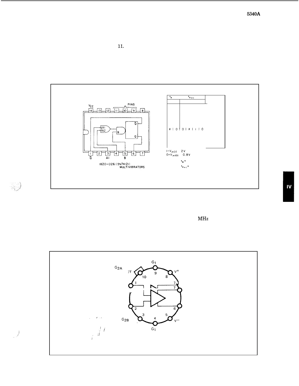
Theory of Operation
XOOXlO
circuit time constants.
An
internal timing resistor
is
available by connecting Vcc (pin
14)
to pin
9,
also
an
external resistor may be used between these two pins. The external timing capacitor
connects between pins
10
and
11.
The output pulse duration
is
determined by the
RC
time con
-
stant of the timing components. The truth table shows the logic states that result in a one
-
shot
output. When the multivibrator fires, the outputs are independent
of
further input transitions
and are dependent only on the timing components.
Figure
4
-
11.
Monostable Multivibrator
1820
-
0261
TIMING PINS
'CC
NC NC
,-fi-,
NC
TRUTH TABLE
'n
INPUT
'nti
INPUT
OUTPUT
INHIBIT
INHIBIT
INHIBIT
ONE SHOT
ONE SHOT
ONE SHOT
ONE SHOT
INHIBIT
INHIBIT
INHIBIT
INHIBIT
INHIBIT
INHIBIT
b
NC Al A2
B
0
NOTES
I
1,
=
TIME BEFORE INPUT TRANSITION
2
In+,
=
TIME AFTER INPUT TRANSITION
3
X
INDICATES THAT EITHER A
1820-
0261
~SN741213
MONOSTABLE MULTIVIBRATORS
LOGICAL
0
OR
I
MAY BE
PRESENT
4
-
29.
Differential
Video
Amplifier
1820
-
0270
4
-
30.
The video amplifier is shown in Figure
4
-
12.
This
IC
consists of a two
-
stage differential
output amplifier with differential inputs.
The unit features
120
MHz bandwidth, selectable
gain and high input impedance.
Gain
is
determined by connecting
a
resistor
from
pin
4 to
pin
9.
For maximum gain, pins
4
and
9
are shorted together.
Figure
4
-
12.
Differential Video Amplifier
1820
-
0270
G1
A
GAIN SELECT
GA .IN
G2A
SELECT
p+
INPUT
1
INPUT 2
G2B
GAIN SELECT
I-
Gl B
GAIN SELECT
Note:
Pin
5
connected
to
case.
OUTPUT
1
OUTPUT 2
4
-
9