Model 5430A
Theory of Operation
TTL
Low
0
to +0.4V
4
-
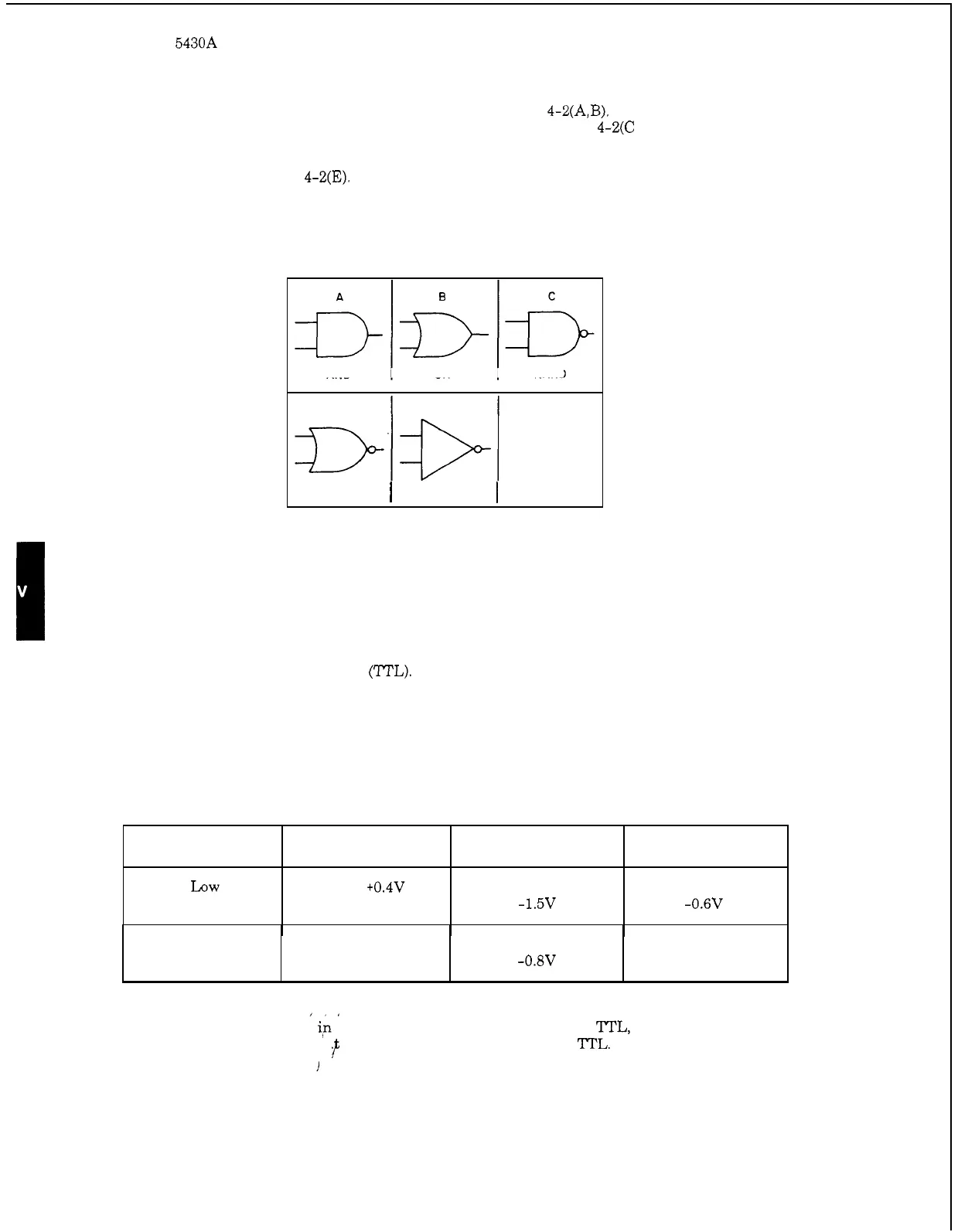
6. INVERSION. AND and
OR
gates are shown in Figure 4-2(A,B). A circle on the output
of
a
logic symbol indicates a LOW when activated
as
shown in Figure 4-2(C and D). Thus,
a
circle
indicates inversion. An AND gate with an inverted output
is
called
a
NAND gate; and
OR
gate
with an inverted output
is
called
a
NOR
gate. A unity
-
gain amplifier with an inverted output
is
called an inverter, Figure 4-2(E).
ECL EECL
approximately
approximately
-1.5V -0.6V
Figure 4
-
2. Gate Symbols
High
AND OR NAND
2.4
to
5V approximately approximately
-0.w
ov
D
E
NOR
I
INVERTER
I
NOTE
Three types of digital signals are present in this instrument. They are:
1.
Transistor Transistor Logic
(WL).
2.
Emitter Coupled Logic (ECL).
3.
Emitter Emitter Coupled Logic (EECL).
Digital signals have two logic states, referred to
as
High and
Low.
The voltage associated with
the High
or
Low
state
is
different for each logic
type.
When logic levels are stated i,n this manual, they
will
be prefaced by 'M'L, ECL, or EECL. When
no preface
is
given, assume tha
the logic level under discussion
is
"L.
f
i
4
-
2