Model 5340A
Theory of Operation
j.:
.)
w
4
-
227.
Sample rate time
is
then started. If U2A (pins
1
and
2)
are high, the front panel Sample
Rate control will determine the delay until the next measurements. Sample rate delay can be
terminated by an ASCII
“J”.
4
-
228. The 5340A can be reset externally by supplying an ASCII “H” to U25. This turns on U9C,
generating a reset through U9B. Moving resolution
switch
A27 between detents also generates a
reset through
U9A if local (front panel control) operation
is
being used.
If
the
5340A
is
in remote
control, U8B detects this and disables
U9A. The output of U14B
is
low for remote operations
and
is
used to light the front panel annunciator.
4
-
229. A20 TIME BASE ASSEMBLY, 05430
-
60073
4
-
230. The 10 MHz oscillator signal connects to A20 pin 5 and
is
divided from
lo7
to 10’ by decade
dividers U24,
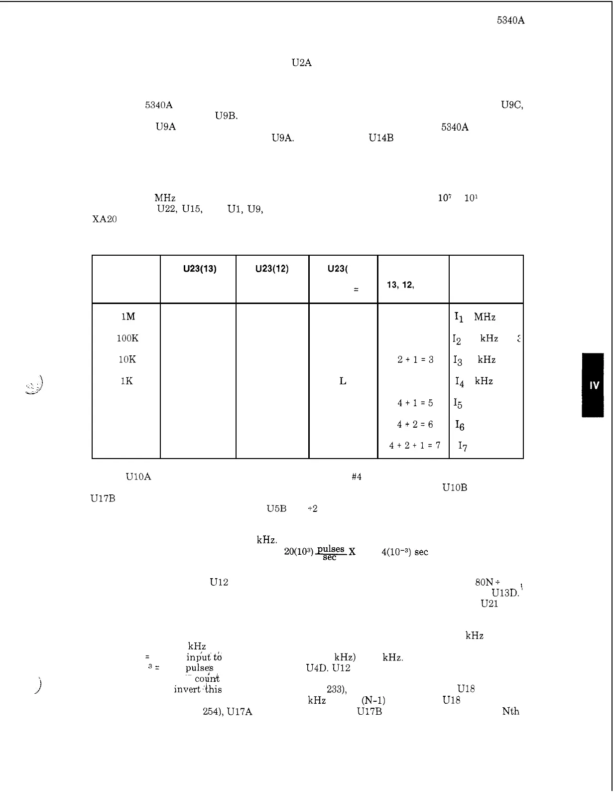
U22, U15, U8, U1, U9, and U16. U23 receives resolution control information at
XA20
pins
F,
E,
and D, and determines which decade divider output
is
selected
as
shown in
Table 4
-
2.
Table 4
-
2. Time Base Signal Selection
Resolution
Switch
Setting
1M
lOOK
10K
1K
100
10
1
U23(13)
Binary
Weight
=
4
L
L
L
H
H
H
H
U23(12)
Binary
Weight
=
2
L
H
H
L
L
H
H
U23( 11)
Binary
Weight
=
1
H
L
H
H
L
H
Equivalent
input
of
pins
13,12, and 11
(H
=
activated]
1
2
2+1=3
4
4+1=5
4+2=6
4+2+1=7
Selected
Signal
11
1
MHz pin
2
12
100 kHz pin
I3 10 kHz pin
4
I4
1
kHz pin 5
I5
100 Hz pin 6
I6 10 Hz pin 7
I7
1
Hz pin
9
4
-
231. UlOA receives the “Main Gate Control”: (Action #4 of program) from the A21 Control
Assembly. This triggers the following sequence of events: UlOA pin 5 Low, UlOB pin 8 Low,
U17B pin 8 High, UllB pin 8 Low, and U4C pin
8
momentarily High. The main gate in A22 opens
upon completion
of
the above sequence. U5B
is
a
12
circuit for the
500
Hz output
of
Ul
and it also
switches U3B for
4
ms (the period of 250 Hz). U3B toggles when
it
receives the “N Gate” com
-
mand (Action
#14
of program) from the A21 Control Assembly. U25
is
a
pulse shaper whose in
-
put frequency from A14 is N times
20
kHz. N equals the harmonic number of the phase lock loops.
“N” Counter Main Gate U4D lets through
20(103)*X N
X
4(10-3) sec
=
80N pulses during
the time U3D
is
switched.
4
-
232. Divide by 10 circuit U12 and divide by 8 circuit U5A provide an output which
is
80N
+
80
=
N. U6 and U7 are binary counters that receive the N count after
it
has been inverted by U13D.
The outputs of U6 and U7 are inverted (one’s complement) and fed to preset counters U21 and
U18.
4
-
233. As an example of operation assume
that
the resolution switch
is
set to
100
kHz causing
U23 to select the 100
kHz signal. Assume also that the phase lock loops are locked on an input
such that
N
=
22. The input to U25
is
a
signal of 22
(20
kHz)
=
440 kHz. When U4D opens for
4
ms,
440 x
4
x 10
=
1760 pu1se;s are passed through U4D. U12 and U5 drive the signal by 80 and the
output is
N.
U6 and U7 coud these pulses and output total in binary, which is 00010110 (Decimal
22). U13 and U14
invert.this to 11101001 (Decimal 233), which gets preset into U18 and U21.
Next U18 and U21 are’released to count the 100
kHz signal.
(N-1)
counts later
U18
and U21 will
be
at
1111
1110 (Decimal 254), U17A pin
6
will go
Low
and U17B pin 8 will
go
High.
On
the Nth
count, UllB pin 8 will go Low, U4C pin 8 will go momentarily High and the main gate closes.
_
-
j
4
-
47